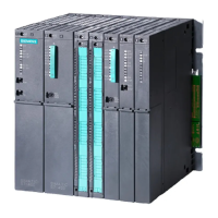
3.3 Installing the FM 450-1
Rules
No special protective measures (EGB guidelines) are required for installing the FM 450-1.
Tools required
You require a 4.5 mm screwdriver to install the FM 450-1.
Installation procedure
Proceed as follows to install an FM 450-1
1. Hook the FM 450-1 in at the top and rotate it down.
2. Screw the FM 450-1 tight (torque approx. 0.8 to 1.1 Nm).
3. Label the FM 450-1 with its slot number. For this purpose use the number wheel enclosed
with the rack.
The system according to which you must perform then numbering and the procedure for
dening the slot number are described in manual /1/.
Further information
Further information on the installation and removal of modules is to be found in manual /1/.
3.4 Removal of the FM 450-1
Rules
No special protective measures (EGB guidelines) are required for removing the FM 450-1.
Tools required
You require a 4.5 mm screwdriver to remove the FM 450-1.
Procedure for removal
Proceed as follows to remove an FM 450-1
1. Release the front connector and pull it out.
2. Undo the module xing screw.
3. Rotate the module out of the rack and unhook it.
4. If necessary, install a new module.
Installation and Removal
3.4 Removal of the FM 450-1
Counter module FM 450-1
22 Equipment Manual, 03/2022, A5E03648739-AC

 Loading...


