DETAILED CASE AND MODULE DESCRIPTION
_________________________________________________________________________________________________________
8-33
SIG-00-22-02 JUNE 2022 (Revised September 2022)
Version: B.1
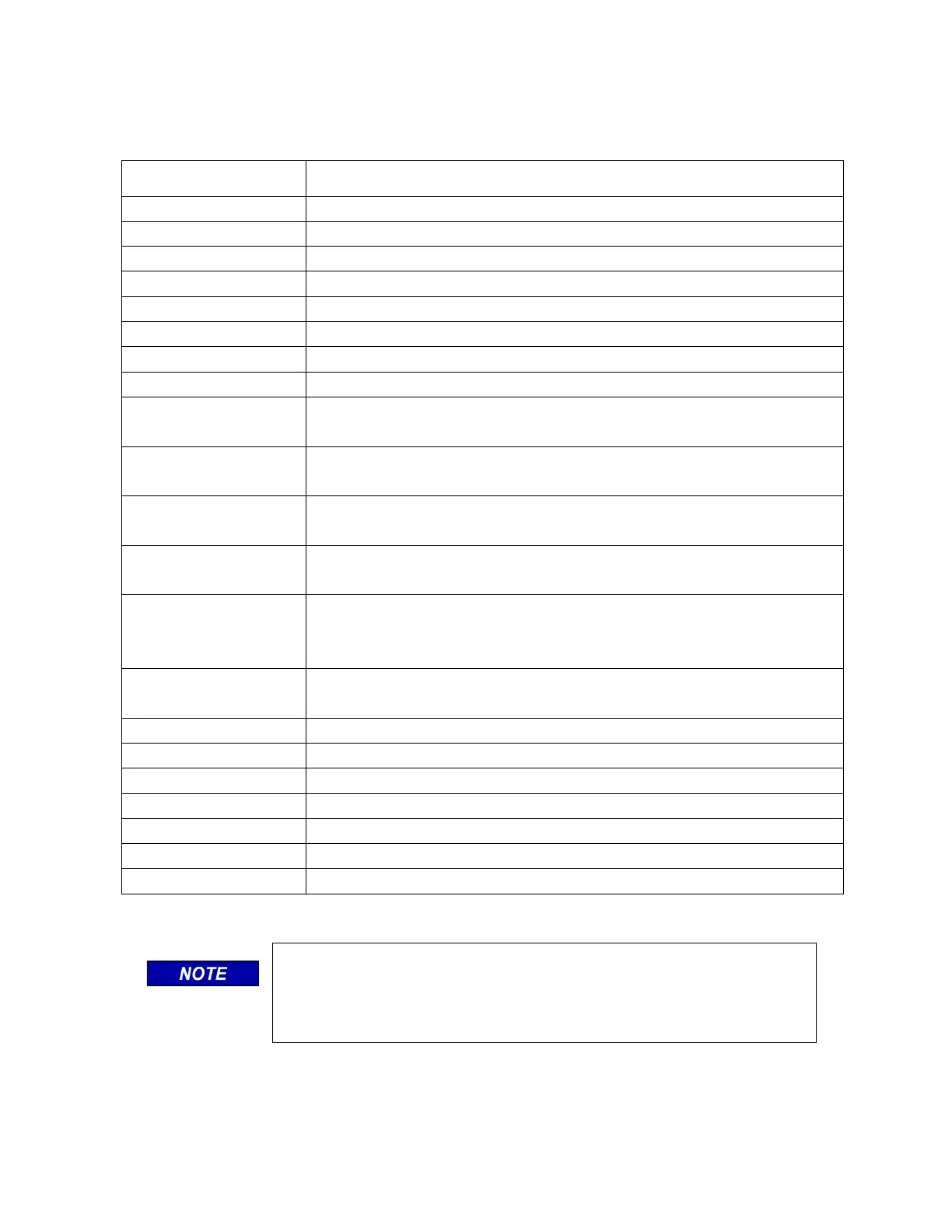
Table 8-16 Display Module Controls, Indicators, Connectors, and Display Descriptions
ITEM DESCRIPTION
2 ½ x 4 inch OLED Color Display
5-key membrane navigational cluster
CPU data stream indicators
TX LED (Green) RX LED (Yellow)
Communications data stream indicators
TX LED (Green) RX LED (Yellow)
SEAR data stream indicators
TX LED (Green) RX LED (Yellow)
Echelon
®
LAN data indicators
TX LED (Green) RX LED (Yellow)
Ethernet Power indicator LED (Green)
Ethernet 1 data indicators (embedded in connector)
Data: TX LED (Green) RX LED (Yellow)
Ethernet 2 data indicators (embedded in connector)
TX LED (Green) RX LED (Yellow)
RJ-45 powered connector (See note)
DB-9, Female Serial connector, RS-232
The Ethernet 1 powered connector is designed specifically for
Siemens Ethernet Spread Spectrum Radios and may not power other
Power-Over-Ethernet (POE) devices.