Product overview
2.1 Properties
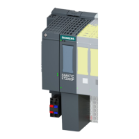
IM 155-6 PN ST interface module (6ES7155-6AU01-0BN0)
12 Manual, 04/2017, A5E03576904-AE
Note
First BaseUnit of an ET 200SP in the configuration
The first BaseUnit of an ET 200SP station may be a dark
As of firmware V3.x, the interface modules support plugging dark-colored BaseUnits in slot
1. This means that modules without a connection to the integrated voltage buses P1 and P2
can now also be configured starting with slot 1. Currently, this applies to the following
modules:
● AI EnergyMeter
● DI 4x120..230VAC ST (6ES7131-6FD00-0BB1)
● DQ 4x24..230VAC/2A ST (6ES7132-6FD00-0BB1)
Requirement for configuration of these modules in slot 1:
● Configuration via GSD or GSDML
● Configuration as of STEP 7 V5.5 SP4 with
– HSP0241 V2.0 for IM155-6 PN ST
– HSP0242 V2.0 for IM155-6 DP HF
– HSP0255 V3.0 for IM155-6 PN HF
● Configuration as of STEP 7 V13 SP1

 Loading...


