Do you have a question about the Siemens IM 155-6 PN ST and is the answer not in the manual?
| Brand | Siemens |
|---|---|
| Model | IM 155-6 PN ST |
| Category | Control Unit |
| Language | English |
Details safety alert symbols and their meanings for hazard levels.
Specifies the necessary training and experience for operating the product.
Provides guidelines for safe and correct product operation, transport, and maintenance.
Lists registered trademarks of Siemens AG and other companies.
States that the publication's consistency is reviewed but variance cannot be guaranteed.
Explains the manual's role as a supplement to the system manual.
Describes the formatting, symbols, and notes used for important information.
Offers guidance on industrial security and protecting against cyber threats.
Covers function manuals for general topics like diagnostics and communication.
Refers to manuals providing detailed information about specific modules.
Points to the system manual and TIA Portal online help for system overview.
Details how to access the complete set of ET 200SP documentation.
Describes the features and benefits of the mySupport online portal.
Explains how to create custom manuals and manage documentation within mySupport.
Covers accessing product data like CAD models, drawings, and master data.
Provides examples and tools for solving automation tasks.
Introduces a tool for selecting, configuring, and ordering automation technology.
Describes a tool for commissioning and maintenance of SIMATIC S7 stations.
Explains PRONETA for analyzing PROFINET networks during commissioning.
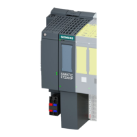
Lists article numbers, view, and key technical properties of the interface module.
Defines system limits and lists optional accessories for the module.
Describes the properties and functions of the included server module.
Guidance on selecting and placing the initial BaseUnit in the configuration.
Details PROFINET IO functions and additional module capabilities.
Outlines the software versions required for configuring module functions.
Advises on setting fixed connection configurations for PROFINET ports.
Explains the synchronized data transmission method for IRT communication.
Describes the PROFINET function for accelerating IO device startup.
Explains how to replace devices without topological configuration.
Details device replacement using topological configuration and LLDP protocol.
Explains the function for safeguarding communication availability using ring topology.
Describes how an IO device can share data with multiple IO controllers.
Enables separate configuration and parameterization of I/O module parts into submodules.
Allows sharing of input/output data between up to two IO controllers.
Details how to monitor the value status of I/O modules.
Explains PROFIenergy for reducing energy consumption during idle periods.
Describes the interface module's support for fail-safe modules.
Covers the interface module's support for specific technology modules.
Explains how configuration control prepares the system for future extensions.
Details the pin assignments for the 24V DC power supply connection.
Specifies the pin assignment for PROFINET IO using the RJ45 BusAdapter.
Specifies the pin assignment for PROFINET IO using the FC BusAdapter.
Presents a block diagram illustrating the module's electrical connections.
Lists the configurable parameters for the interface module as defined in the GSD file.
Explains the parameter used to enable the configuration control function.
Describes how output values are handled by the IO controller during fault conditions.
Details how to read the status of the supply voltage L+ for I/O modules.
Provides an overview of the LEDs on the interface module and BusAdapter.
Explains the meaning and remedies for the RN, ER, MT, and PWR LEDs.
Details the status indications for the LK1/LK2 LEDs on the BusAdapter.
Describes how configuration errors are indicated by the ERROR and MAINT LEDs.
Explains the sequence and priority of LED error signaling.
Maps error codes and locations to their causes and recommended remedies.
Covers diagnostics, hardware, and swapping interrupts and their processing.
Introduces system diagnostics available in STEP 7 for automation systems.
Explains how module events trigger diagnostics interrupts.
Details the conditions that trigger hardware interrupts.
Describes the process by which swapping interrupts are triggered.
Outlines the actions taken and data reporting for diagnostics alarms.
Describes methods for retrieving diagnostic data using STEP 7 tools.
Lists common causes and troubleshooting steps for diagnostics alarms.
Signals indicating when network components may need checking or replacement.
Provides information on diagnosing channel faults within modules.
Details the coding scheme for extended channel diagnostics from firmware V3.3.0.
Describes the structure of diagnostics data records based on Block Version.
Explains how manufacturer-specific diagnostics are signaled via the User Structure Identifier.
Details the USI structure for diagnostics related to supply voltage failure.
Details the USI structure for diagnostics related to a missing server module.
Details the USI structure for diagnostics when multiple I/O modules are pulled.
Details the USI structure for diagnostics related to incorrect BaseUnit installation.
Details the USI structure for diagnostics related to incorrect bus configuration.
Identifies invalid states that can lead to device failure or data exchange issues.
Describes module reactions to the loss of supply voltage L+ on a BaseUnit.
Covers handling controller stop states and recovering IO devices.
Compares functional differences between IM 155-6 PN ST firmware versions.
Details compatibility of supply voltage status reporting for various modules.
Defines how to calculate maximum reaction times for fail-safe modules.
Provides comprehensive technical data including general info, supply, input, and power.
Details address space, rack limits, submodule counts, and interface types.
Lists services, communication modes, and diagnostics indicators for PROFINET IO.
Presents technical specifications for the BA 2xRJ45 BusAdapter.
Presents technical specifications for the BA 2xFC BusAdapter.
Contains dimension drawings showing the module's physical size and installation requirements.


