9/73
Building Technologies Division Basic Documentation LME39… CC1P7106en
1 Safety notes 08.12.2017
1.5 Connection BCI via integrated jack RJ11
If the BCI (jack RJ11) is not used, protection against electric shock hazard must be
provided (jack must be covered up)
The AGV50... signal cable for the AZL2… or other accessories, for example BC
interface OCI410 (plugs into the jack RJ11), must be connected or disconnected
only when the burner control is dead (all-polar disconnection), since the BCI does
not ensure safe separation from mains voltage
The display and operating unit AZL2... is designed for direct connection to the
integrated jack RJ11 at LME39...
Since the BC interface has no safe separation from mains voltage, the signal cable
AGV50 must conform to certain specifications. Siemens has specified the signal
cable AGV50 for use under the burner hood; refer to Technical data. When using
other signal cables, it is not guaranteed that the required cable features will be
available.
Do not lay the signal cable AGV50... from the LME39… to the AZL2… together with
other cables (especially high-voltage ignition cable)
Service operation with a longer signal cable from LME39… to AZL2…, or from
LME39… to OCI410:
If a longer signal cable is required for service work for example (short-time,
<24 hours), note that above usage under the burner hood no longer applies and, for
this reason, the signal cable can be subjected to increased mechanical stress. In
that case, extra cable sheathing is required (e.g. heat shrink tubing)
Both the signal cable AGV50... and the AZL2… must be shipped and stored so that
no damage due to dust and water can occur when used in the plant later on
To ensure protection against electric shock hazard, make certain that, prior to
switching on power, the signal cable AGV50... is correctly connected to the AZL2…
The AZL2… must be used in a dry and clean environment
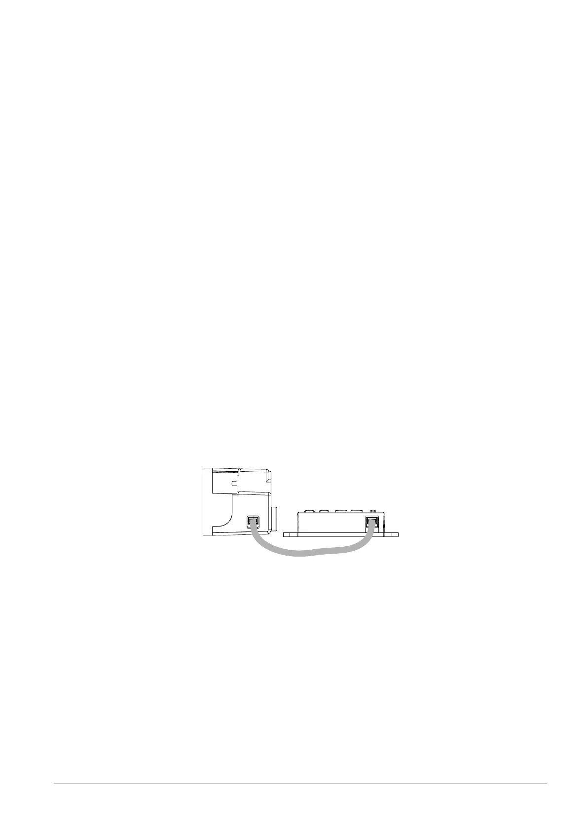
Connection display and operating unit AZL2...
Connect the AZL2... with the interface at your LME39..., follow the example design
below
LME39...
AZL21...
7106z178e/0708
Signal cable
Figure 2: Connection display and operating unit AZL2
 Loading...