6. SYSTEM PARAMETERS English
Parameter Function Range
[Default]
Description / Notes
© Siemens plc 1999 G85139-H1751-U529-D1
45
4/8/9
P018 ·
Automatic restart after fault 0 - 1
[0]
Automatic restart after fault:
0 = Disabled
1 = The inverter will attempt to restart up to 5 times after a fault. If the
fault is not cleared after the 5th attempt, the inverter will remain in
the fault state. The display flashes during this condition.
WARNING:
While waiting to re-start, the display will flash. This means
that a start is pending and may happen at any time. Fault
codes can be observed in P140 and P930.
P019 ·
Skip frequency bandwidth (Hz) 0.00 - 10.00
[2.00]
Frequencies set by P014, P027, P028 and P029 that are within +/- the value
of P019 of all skip frequencies are suppressed.
P021 ·
Minimum analogue frequency (Hz) 0 - 650.00
[0.00]
Frequency corresponding to the lowest analogue input value, i.e.
0 V/0 mA or 2 V/4 mA, determined by P023 and the settings of the DIP
selector switches 1, 2 and 3 (see Figure 4.1.2). This can be set to a higher
value than P022 to give an inverse relationship between analogue input and
frequency output (see diagram in P022).
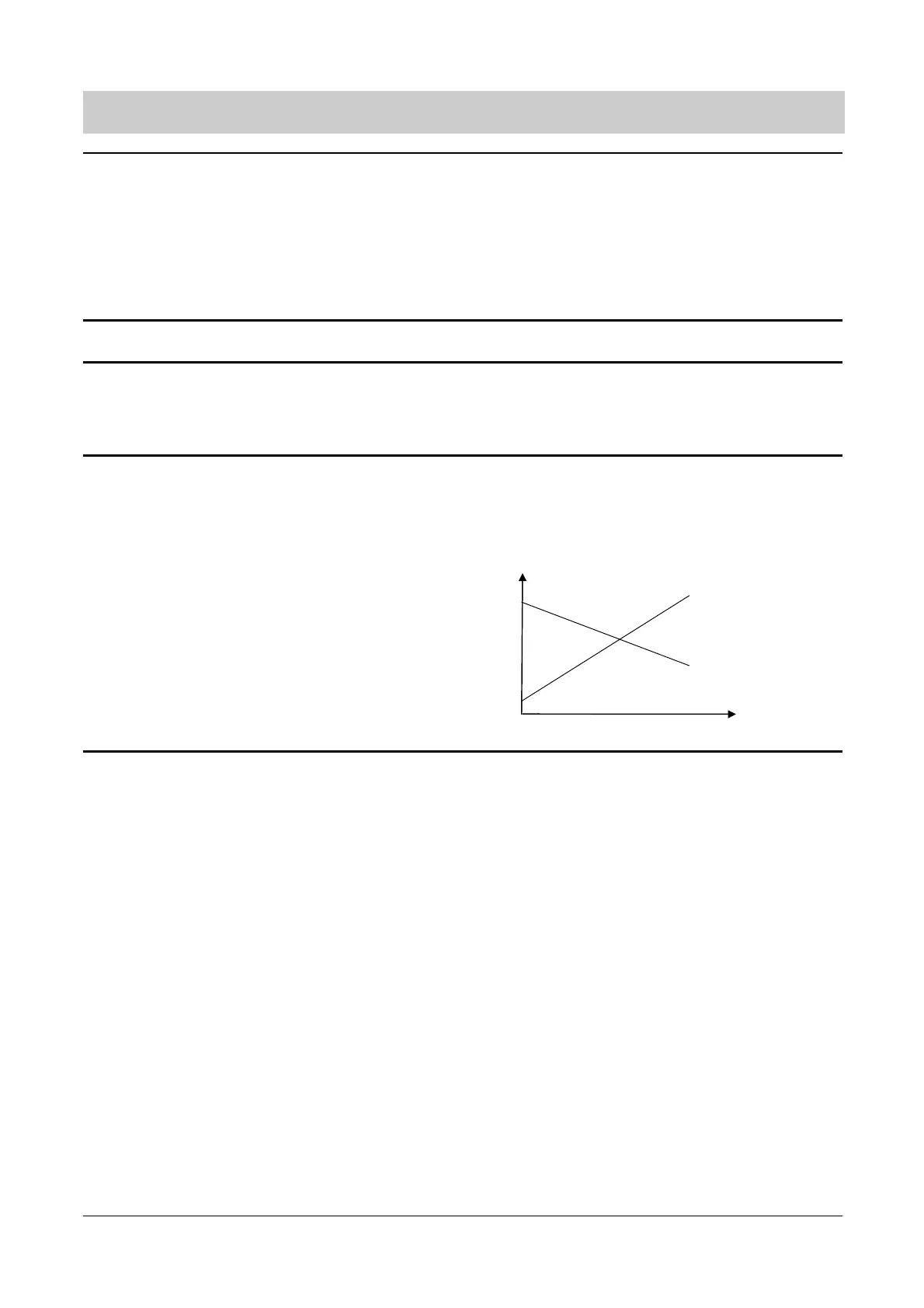
P022 ·
Maximum analogue frequency (Hz) 0 - 650.00
[50.00]
Frequency corresponding to the highest analogue input value, i.e.
10 V or 20 mA, determined by P023 and the setting of the DIP selector
switches 1, 2 and 3 (see Figure 4.1.2) This can be set to a lower value than
P021 to give an inverse relationship between analogue input and frequency
output.
i.e.
Note: The output frequency is limited by values entered for P012/P013.
f
V/ I
P021
P021
P022
P022