English 6. SYSTEM PARAMETERS
Parameter Function Range
[Default]
Description / Notes
G85139-H1751-U529-D1 © Siemens plc 199
4/8/99
46
P023 ·
Analogue input 1 type 0 - 3
[0]
Sets analogue input type for analogue input 1, in conjunction with the settings
of the DIP selector switches 1, 2 and 3 (see Figure 4.1.2). :
0 = 0 V to 10 V/ 0 to 20 mA Unipolar input
1 = 2 V to 10 V/ 4 to 20 mA Unipolar input
2 = 2 V to 10 V/ 4 to 20 mA Unipolar input with controlled start /
stop when using analogue input control.
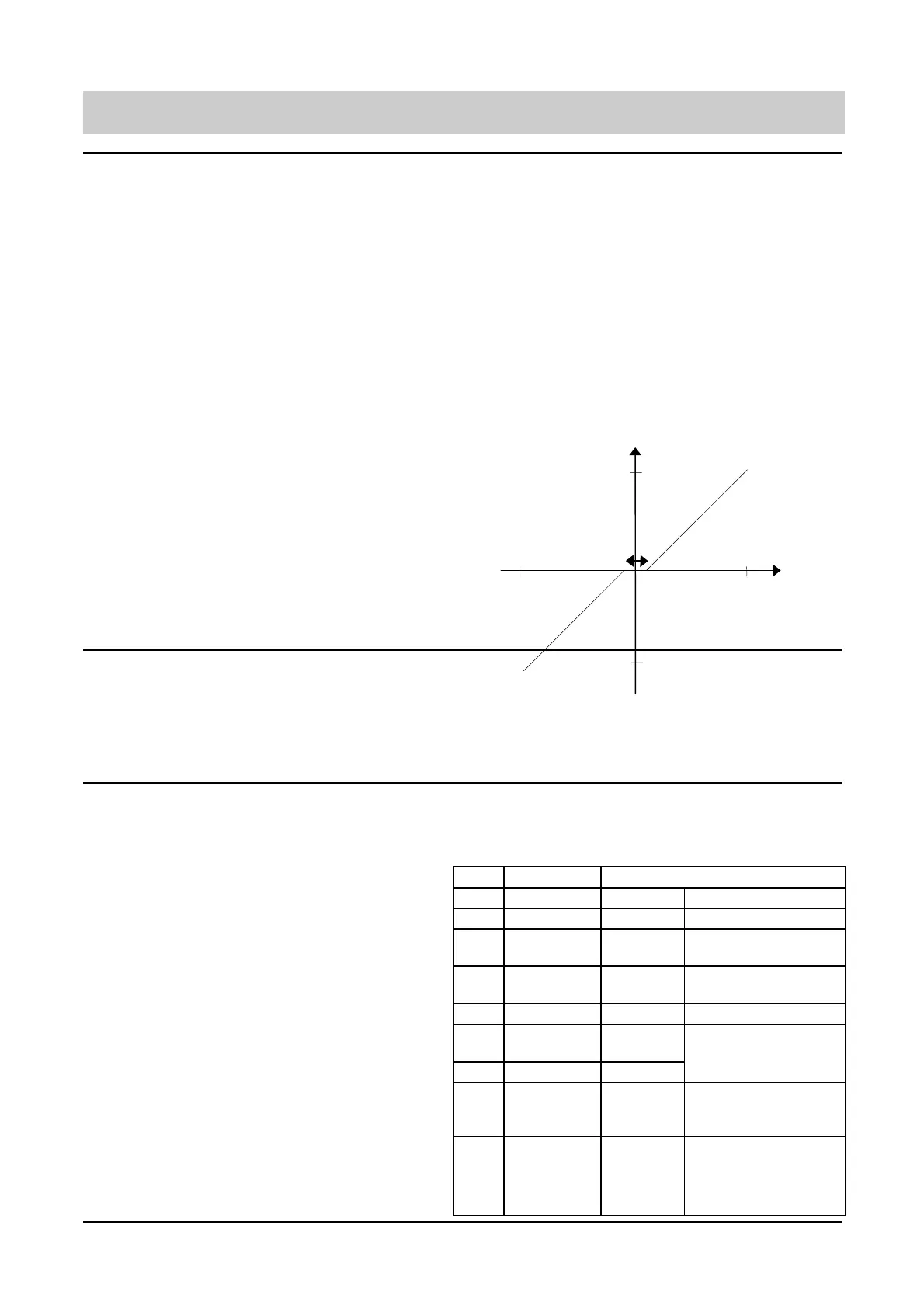
3 = -10V to +10V Bipolar input. -10V corresponds to left rotation at speed
set in P021, +10V corresponds to right rotation at speed set in P022
Note: Setting P023 = 2 will not work unless the inverter is under full local
control (i.e. P910 = 0 or 4) and V ³ 1 V or 2mA.
WARNING: The inverter will automatically start when voltage goes
above 1V. This equally applies to both analogue and digital
control (i.e. P006 = 0 or 1)
Bi-polar Input Operation
P024 ·
Analogue setpoint addition 0 - 2
[0]
If the inverter is not in analogue mode (P006 = 0 or 2), setting this parameter
to:
0 = No addition to basic setpoint frequency as defined in P006.
1 = Addition of analogue input 1 to the basic setpoint frequency as
defined in P006
2 = Scaling of basic setpoint (P006) by analogue input 1 in the range
0 -100%.
P025 ·
Analogue output 1 0 - 105
[0]
This provides a method of scaling the analogue output 1 in accordance with
the following table:
Use range 0 - 5 if minimum output value = 0 mA.
Use range 100 - 105 if minimum output value = 4 mA
P025 =
Selection
Analogue Output Range Limits
0/4 mA 20 mA
0/100
Output frequency 0 Hz Output frequency (P013)
1/101
Frequency
setpoint
0 Hz Frequency setpoint (P013)
2/102
Motor current 0 A Max. overload current
(P083 x P086 / 100)
3/103
DC-link voltage 0 V 1023 Vdc
4/104
Motor torque -250% +250%
(100% = P085 x 9.55 / P082 Nm)
5/105
Motor RPM 0 Nominal motor RPM (P082)
6/106
Motor
magnetising
current
0 A Max. overload current
(P083 x P186 / 100)
7/107
Motor torque
producing
current
(centre zero)
0 A
Max
regenerative
torque
Max. overload current
i.e. accelerating torque
(P083 x P186 / 100)
F max
F min
+10V
0.2V Hysteresis
-10V
P021
P022