MJ-5 Communications Module
7
To further protect against external electrical interference, the pair is shielded by a grounded outer covering. The
shield conducts radio frequency interference (RFI) to the ground, thus reducing its effect on the twisted pair.
Concern over RFI and EMI is important given the high electrical current and electrically noisy environment through
which the communication wires are routed.
Follow the rules below to properly install the RS-485 cables.
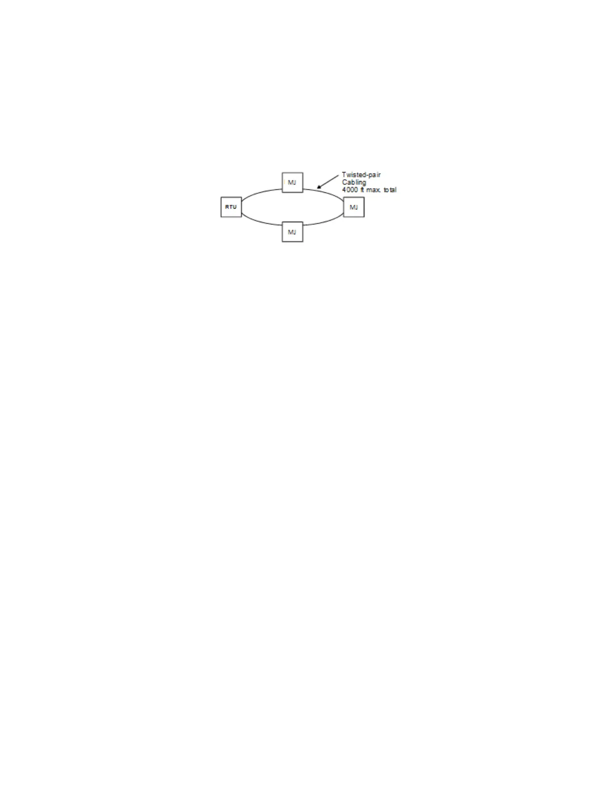
1. Connect all field devices in a loop technology so that all devices are connected to the master in case of a line
break. The basic loop topology is shown below.
Figure 5-4: RS-485 Loop Topology
One of the advantages of the loop topology is that if a line is cut, communication is not interrupted. By
completing the loop in the RS-485 cable, one break can be made anywhere in the line without compromising
communication with the master device (RTU). To maintain redundancy, avoid open ended runs of the bus.
Each installation method (see Figures 2-4 to 2-6) has advantages and disadvantages. The loop method requires
more cable than does the single-ended run method. This extra cable is needed to run from the last device on the
run to the master device (RTU). The additional cable adds expense and shortens the total distance the farthest
device can be located from the master device. The advantage of the loop method is in the ability to
communicate with all devices when there is a break in the loop.
The single-ended run allows larger distances between the master device and the farthest slave device, but it does
not allow the master device to communicate with devices on the far side of a break. This method also requires
the use of terminating resistors.
2. A maximum of 32 devices may be connected in a single RS-485 bus with a total cable run no longer than 4000
feet.
3. Always ground the shield at only one end of a cable segment. For all devices, ground the cable shield at one end
only to prevent induced interference that may result from circulating ground currents. If a cable’s shield is
grounded at both ends, a ground lop can exist between the components. This ground loop can result in induced
interference that causes signal distortion. Figure 7-2 shows the proper method for terminating the shield at the
Communications Module connector.
4. When the Communications Module is mounted in the MJ-5 Control Panel, it is grounded internally through the
MJ-5 to the equipment ground. A separate connection to the equipment ground is not required.
5. The recommended twisted-pair cable for an RS-485 bus has a characteristic impedance of 120 ohms. Any
change in the type of cable, or an open-ended length of cable, creates a discontinuity in the impedance and
causes a reflection. Placing resistors that match the characteristic impedance of the cable at the open end of a
twisted-pair stub eliminates reflection.
For long, single-ended runs (over 1000 Forwarding ft.), you may need to install a 120 ohm terminating resistor
between the data (+) and (-) terminals of the farthest device from the RTU or master end. Adding the
terminating resistor is not an absolute requirement, but using it minimizes reflected interference on the
communication cable.
6. Do not route signal cabling parallel to power conductors. Wherever possible, place the communication cable
perpendicular to the power conductor as shown below. Power conductors are any cables or bus conductors
carrying currents greater than 20 amperes.

 Loading...


