MJ-5 Communications Module
5
5.1 Fiber Optic Cable Type
The recommended cable is 62.5/125 m diameter fiber optic cable with a maximum attenuation of 5dB/km at a
wavelength of 820-850 nm. If this is not available use 50/125 m diameter glass cable, but only for cable lengths
less than 1500 feet. Use of 50/125 m diameter cable requires that the range jumper J12 be set for long range. This
will provide protection against under driving the receiver. When using 50/125m cable, install the long range
jumper (J12) even for very short cable lengths.
A 100/140 m diameter cable can also be used for cable lengths less than 1500 feet. Use of this cable requires that
the range jumper (J12) be set to normal. This setting will provide protection against overdriving the receiver.
Plastic cable is not recommended due to the coupling efficiency of the cable, which at short lengths will overload
the optical receiver. In addition, the large cable attenuation normally associated with plastic cable limits the useful
link lengths to a fraction of that achievable with glass cable.
5.1.1 Fiber Optic Cable Lengths
Calculate cable length by determining the output power of the transmitter (P
TX
) and the input receive level (Peak
Input Power Logic Level Low Receiver Sensitivity, P
RX
). The difference between the two numbers is the optical
power budget (P
B
’).
P
B
’ = P
TX
– P
RX
For example, if transmitter output power is -16 dBm and the input receive level is -24 dBm, the optical power
budget is then 8 dBm. Subtract from this value the fixed losses (i.e. connector losses, splice losses, P
Loss
) to obtain
the real power budget (P
B
).
P
B
= P
B
’ – P
Loss
Divide the result by the cable attenuation (Att) in dB/km to arrive at the maximum cable length. Note that the
transmitter output power data given in the specifications already includes connector loss when using precision
ceramic ST connectors.
Length = P
B
/ Att
5.1.2 Fiber Optic Connector
The fiber optic cables (or “patch cords”) used with the MJ-5 Fiber Optic Communications Module must be
terminated with ST style connectors and have a numerical aperture of 0.275 ± 0.015.
(If pre-terminated cables are not used, follow the instructions supplied by the manufacturer to attach the connector to
the fiber cable using the cable type recommended in section 7.1.)
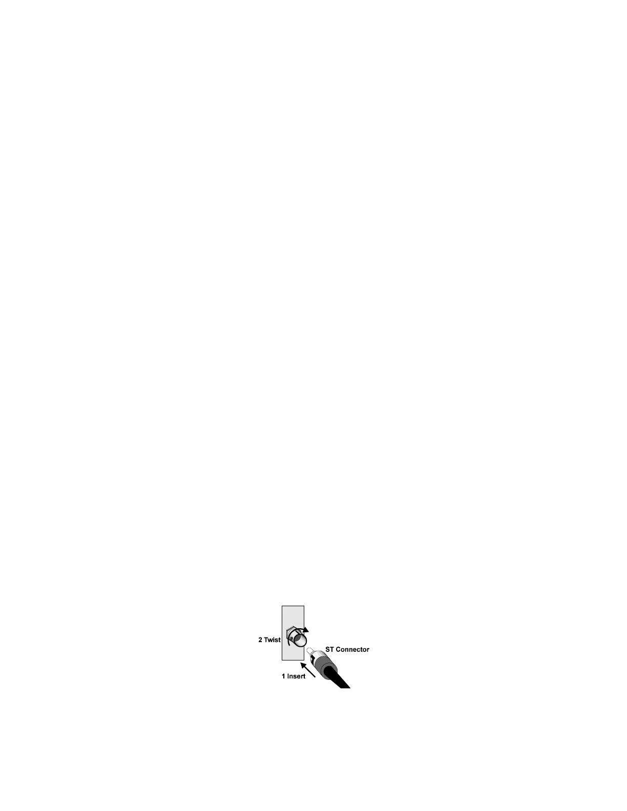
5.1.3 Fiber Optic Connections
When making connections to the transmitter and receiver inputs/outputs, ensure that the transmit output from one
device is connected to the receive input of the next device. Figure 7-1 shows how to insert the connector. The tip of
the cable on the ST connector must be clean and free of dust. Dust on the tip of the cable will cause signal
attenuation.
Use care when handling the fiber optic connector, especially the exposed ceramic ferrule.
Figure 5-1: Fiber Optic Connections

 Loading...


