8
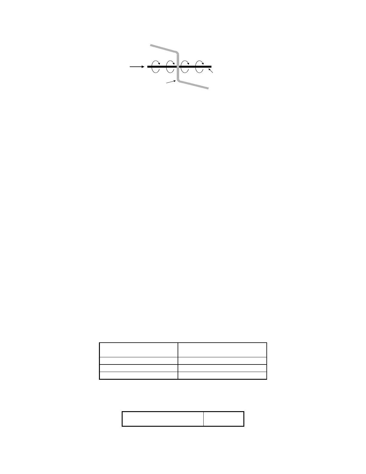
Figure 5-5: Communication Cable Routing
Electrical current flowing through a conductor forms a magnetic field around the wire as shown above.
Interference is coupled into the wires in the cable through electromagnetic fields. Just as current through a wire
causes a magnetic field to form around it, a magnetic field can cause current to flow in a wire. This induction of
current is a function of the geometry or orientation of the wires. If the communication cable is at a right angle
with the power conductor, it is aligned with the direction of the magnetic field and no current is induced.
7. Follow these guidelines when you route communications cables between electrical equipment:
Run communications cables in the same cable raceways (cable routes, cable trays, or cable gutters) as
unshielded digital and analog signal cables up to 60 V.
Run communications cables in the same cable raceway with shielded signal and supply cables up to 230 V.
Run communications cables 4 inches away from unshielded signal and supply cables of up to 230 V.
Run cables with voltages greater than 230 V in separate ducts (routes, conduits).
5.3 RS-232 Connections
The following section describes the connection requirements for RS-232 cable. This cable will allow you to connect
the MJ-5 Control Panel to an RTU or personal computer.
Five of the standard RS-232 wires are used for this application.
Signal Return (RTN)
RXD
TXD
CTS
RTS
Table 7-2 lists the connections that must be made to connect the RS232/485 interface to a personal computer, RTU,
or other supervisory device. The MJ-5 Communications Module defaults to no-handshaking-required mode.
However, the communications module asserts RTS while it transmits data, but the module will ignore the CTS input
signal.
Table 5-2 RS-232 Intelligent Electronic Device Wiring
MJ-5 RS-232/485
Communications Interface
Personal computer, supervisory
device, or other network device
Table 7-3 lists the connections that must be made to connect the RS232/485 interface to a modem.
Table 5-3 Modem Wiring
MJ-5 RS-232/485
Communications Interface
Current
Flow
Magnetic Field
Around Conductor
Electric Power
Conductor
Communication Cable

 Loading...


