MJ-5 Communications Module
1
1 Introduction
This manual describes the installation and connection procedures for the MJ-5
TM
Communications Module which
has the Fiber Optic and RS-232/485, and networking interfaces combined in one single printed circuit board. The
operation and functionality of the Fiber Optic and the RS-232-/485 interfaces are quite similar, only one of the
interfaces can be used at a time. The manual covers the procedures for connecting the module to a system of
networked MJ-5 Tap Changer Control Panels.
1.1 Description
The Siemens MJ-5 Communications Module is the communication interface used to connect the MJ-5 Control Panel
to a network of regulator controllers, control devices and supervisory equipment. Figure 1-1 illustrates the MJ5
Communications Module.
The fiber optic interface enables connection of the tap changer control panel to the supervisory equipment via
multimode fiber optic cable. The RS-232/485 interface enables connection of the tap changer control panel to the
supervisory equipment via electrical wire.
The MJ-5 Communications Module is installed in MJ-5 Tap Changer Control Panels. This allows you to easily
network the control panels and other field devices to a remote terminal unit (RTU) or other supervisory device. An
adapter kit is available for mounting MJ-5 Communications Modules in MJ-X Control Panels.
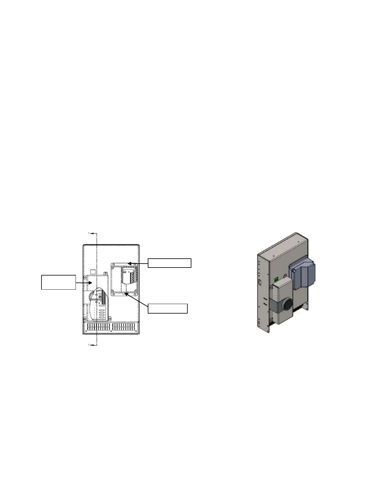
Figure 1-1: MJ-5 Communications Module Figure 1-2: Back of MJ-5
2 Transmission Methods
There are two transmission mediums available for sending data to the RTU:
fiber optic
wire
2.1 Fiber Optic Transmission
The primary benefits of fiber optic communications are its immunity to induced electrical interference and relatively
low signal loss. Electrical noise cannot be induced into the cable to generate transient spikes that disrupt data
communications.

 Loading...


