2 Using the MJ-5 Operator Panel and Controls
Siemens Industry, Inc. 7
U2 P2 Key
Press this key to toggle between the U2 and P2 voltages
when the setting under <ADV CONFIGURE> menu U2/
P2 out is set to Toggle.
Neutralite Test Key
Press this key to illuminate the Neutralite Indicator. This is
an LED test.
Drag Hands Reset Key
Press this key to reset the electromechanical drag hands on
the Position Indicator to the present tap changer position.
This also resets the electronically stored max/min. tap
position values (viewable from the display).
Quick Key
Press this key to view the items stored in the Quick List.
The user-defined Quick Key can display up to 15 different
commonly referenced screens. To set a screen to the Quick
List, first navigate the menu to display the desired screen.
Press and hold the Quick Key for 3 seconds. After which, a
notification will show Quick added.
Note: The Quick Key is supported with MJXplorer version
6, however it is not supported with version 5. See Section
4.10 for how to setup this functionality.
Remote/Local Key
Press this key to enable or disable remote control of the
control panel. The Remote Disabled LED indicates the
status of Remote control.
2.4 Indicators
The front panel also provides user information via
individual status indicators. These indicators provide a
direct means of assessing operational status.
Alert LED
This indicator is illuminated whenever one or more alerts
are active. The indicator may either flash or remain on
steadily.
If flashing, it indicates that one or more alert
conditions are active and have not yet been
acknowledged.
If the Alert Indicator glows steadily, it means that a
previously-acknowledged alert condition continues to
exist.
To acknowledge an Alert, view the Alert screen with the
Alert button and then press the Cancel/Reset button.
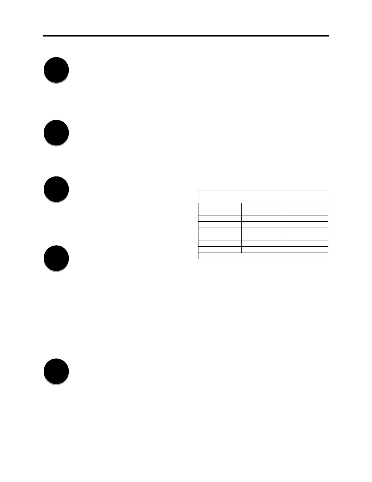
Reverse Power Flow LED
The Reverse Power Flow (RPF) indicator is illuminated
when the microprocessor senses reverse power flow. The
indicator will either be off, on, or flashing depending upon
both Power Flow mode and Current direction. See Section
4.3.11 and Table 2.1 below.
If the real component of load current drops below 1% of the
rated current, then RPF indicator continues to display its
previous state.
If the real component of current is less than 1% when the
MJ-5 Control Panel is powered up, the RPF LED is OFF
(indicates forward).
Remote Auto Inhibit LED
This indicator is illuminated when automatic tap changes
are inhibited. Either the remote operator has sent an
automatic inhibit command, the Automatic Inhibit contacts
have been activated, or a local operator has pressed the
Auto/Manual push-button.
Remote Disabled LED
This indicator is illuminated when Remote control is
disabled. When Remote control is enabled a remote
operator can change the settings, configuration, and control
the regulator remotely. When Remote control is disabled, a
Reverse Current Forward Current
Neutral R On Off
Idle R On Off
Co-Gen On Off
Bi-Dir On Off
F Lock Flashing Off
R Lock On Flashing
1. (Real component) exceeds 1% rated current for 5 seconds
Table 2.1 Reverse Powere flow Indicator Status

 Loading...


