2 Using the MJ-5 Operator Panel and Controls
Siemens Industry, Inc. 10
Voltage Calibration Binding Posts
These binding posts can be used with an external voltmeter
to monitor regulator P2 or U2 voltage. Displaying “U2
Cal” or “P2 Cal” in the <DIAGNOSTICS> menu defines
the voltage (U2 or P2) you can read at these binding posts.
The binding posts are dual banana-style receptacles.
Note that the voltage measured at these binding posts is not
turns-ratio corrected. By contrast, the metered voltage
presented on the display screen (under <METER>) is
corrected by control-program software (see Section 4.3.7
and Section 4.3.8 for configuring the voltage transformer
U2/P2 turns ratio).
2.7 Fuses
Power Fuse
This 6.0 Amp fuse protects the MJ-5 Control Panel circuit
and the tap changer motor circuit.
External Power Source Protection Fuse
This 6.0 Amp fuse protects the MJ-5 Control Panel circuit
and the tap changer motor circuit when powered through
the external source binding posts.
2.8 Terminal Strip Connections
Complete descriptions of all terminal contacts are
provided in Appendix K.
Terminal strips are located on the lower back side of the
MJ-5 Control Panel. These terminals can be used to provide
access to certain microprocessor and other control
functions.
The terminal strips include four terminal pairs for VRC
control and external inhibit function. The terminal strips
include the Current Circuit terminal pair.
Each terminal strip contact is screw type, to facilitate
connection and disconnection of external wiring.
Current Circuit Terminal Contacts
The nominal 200 mA secondary of the regulator current
transformer (CT) is routed through these terminals labeled
C and C2. This terminal pair is provided with a removable
shorting bar to accommodate auxiliary apparatus. These
terminals are shorted at the factory and must remain shorted
unless an appropriate external device is attached.
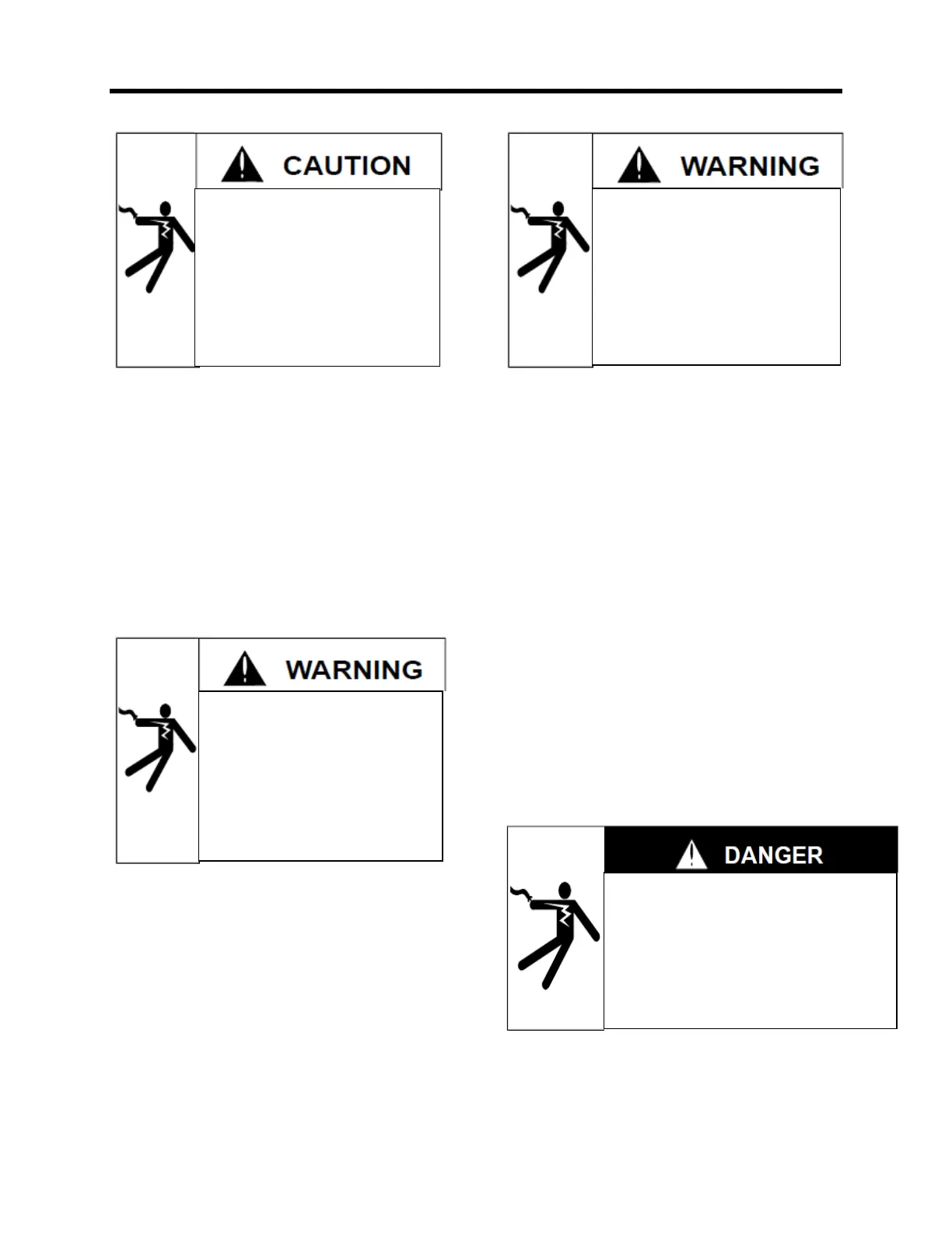
Open CT secondary will result in high
voltage at CT terminals.
Will result in death or serious injury including
equipment damage.
To prevent:
Do not operate with CT secondary open. Short
circuit or apply burden at CT secondary (C2-C)
during operation.
Hazardous voltage present on various
control leads when regulator is energized.
Could result in death or serious injury
including equipment damage from
contact with live line conductors
To prevent:
Bypass the regulator and de-energize
before removing accessory items from the
control box.
Voltage applied at calibration terminals
may energize regulator with high voltage
through voltage transformer.
Could result in death or serious injury
To prevent:
Do not connect any voltage source at the
voltage calibration terminals.
Improper external power connection will
place 120V on the ground circuit.
May result in minor or moderate injury
including equipment damage.
To prevent:
Observe proper polarity of external
power supply.

 Loading...


