5
Mounting/Installation
Connecting the detector base
56
Building Technologies A6V10367521_h_en_--
Fire Safety 2015-02-02
5.10.2 Connection diagram (C-NET-Ex)
WARNING
Connecting cables in environments at risk of explosion
Risk of explosion
Only connect cables in an environment that is not at risk of explosion.
The following applies to C-NET-Ex detector lines:
l Only stubs are permitted.
l The detector line must start with a line adapter (Ex) FDCL221-Ex.
l Observe the maximum number of detectors that may be operated on a stub.
l External alarm indicators may only be connected to one detector.
l Only connect passive, external alarm indicators with negligibly low inductance
and capacitance levels. The external alarm indicators FDAI9x-Ex conform to
these requirements.
The connection is established from base to base using twisted or non-twisted wire
pairs.
+
-
+
-
+
-
C-NET-Ex
2
FDCL221-Ex
C-NET
+
-
1
+
-
Connection diagram for addressed detector line C-NET-Ex with and without external alarm indicators
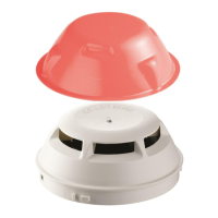
External alarm indicator FDAI9x
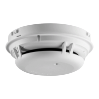
Detector base FDB221, FDB222
Assignment of terminals in detector base

 Loading...