Dyna-Flo Control Valve Services Ltd.
Phone: 780 • 469 • 4000 | Toll Free: 1 • 866 • 396 • 2356 | www.dynafl o.com
P-PS2Q0619A
19
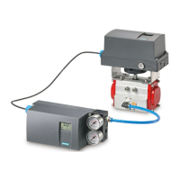
QUARTER TURN MOUNTING INSTRUCTIONS
Mount all hardware as shown in Figure 9. Quarter Turn Actuator Mounting Parts List
is on Table 5. To mount a Siemens PS2 to an Quarter Turn Actuator, follow these
steps:
1 Adhere indicator sticker (Key 3B) onto the mounting bracket (Key 4) in the
center of the centering hole (Refer to Figure 9.2).
2 Attach the mounting bracket (Key 4) (actuator specifi c) onto the rear of the
positioner and secure using lock-washers (Key 7) and hex cap screws (Key 6).
3 Push the coupling wheel (Key 1) onto the input shaft, pull it back by about 1
mm and tighten the hex socket cap screw (Key 10) with the appropriate hex
key.
4 Place the carrier (Key 2) onto the end of the actuator and secure it using a
washer (Key 9) and Fillister head screw (Key 8).
5 Carefully place the positioner with the mounting bracket onto the actuator
such that the pin of the coupling wheel engages in the driver.
6 Align the positioner/mounting bracket assembly in the center of the actuator
and screw tight.
7 Follow start-up as described in this handbook or in the Chapter on
“commissioning” of the Siemens SIPART PS2 Operating Instructions Latest
Edition. Drive the actuator to the end position and adhere scale (Key 3A) on
the coupling wheel (Key 1) according to direction of rotation and rotary
actuator.
Table 5
Basic Quarter Turn Rotary Actuator Mounting Parts List
Key Description
1 Coupling Wheel
2 Carrier
3A Scale
3B Indicator Sticker
4 Mounting Bracket
6 Hex Cap Screw
7 Lock-washer
8 Fillister Head Screw
9 Washer
10 Hex Socket Cap Screw