Dyna-Flo Control Valve Services Ltd.
Phone: 780 • 469 • 4000 | Toll Free: 1 • 866 • 396 • 2356 | www.dynafl o.com
P-PS2Q0619A
ROTARY MOUNTING INSTRUCTIONS
Tools Required:
• Wrenches (5/16”, 3/8”, and 10 mm)
• Slotted Screwdriver
• Phillips Screwdriver
• Terminating Screwdriver
• Hex Wrench Set
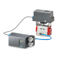
For Rotary Valves mount all hardware as shown in Figures 7 - 8.
Mounting Parts listed in Table 4. To mount a Siemens PS2 to a Rotary Actuator,
follow these steps:
1 Remove the old machine screws (Key 7), old travel indicator (Key 5), and two
hex cap screws (Key 8) from the actuator cover plate (Key 12).
2 Place the valve/actuator in the closed position. Set the travel indicator (Key 5)
over the pin of the pin assembly (Key 6) and place them both onto the
actuator hub. Align the travel indicator with the closed position of the actuator,
thread in the travel indicator screws; completely tighten the travel indicator
and pin assembly to the actuator hub while maintaining the alignment of the
indicator with the closed position of the actuator.
3 Align the mounting bracket (Key 1) to the back of the Siemens positioner so
that the four screw holes match the holes on the positioner as described in
Figures 7 or 7A. Install the lock-washers (Key 2) and cap screws (Key 3)
and completely tighten the bracket to the positioner.
4 Slide the coupler (Key 4) onto the input shaft (Key 13) of the positioner, the
fl at of the PS2 input shaft does not matter to the orientation of the coupler.
Hand tighten the coupler screw (Key 4A) using the appropriate hex key. Do
not over torque the coupler screw, over torquing can damage the coupler.
5 Place the spacers (Key 11) over the holes on the actuator cover plate. Place
the PS2/mounting bracket assembly onto the actuator being careful to have
the coupler fi t over the pin assembly (Refer to Figure 8). Slide the two
lock-washers (Key 10) onto the mounting cap screws (Key 13). Insert the cap
screws through the bracket (Key 1) and spacers (Key 11) and into the actuator
cover plate holes. Completely tighten the cap screws and then completely
tighten the 2nd coupler screw (Key 4A) securing it to the pin assembly.
6 Follow start-up as described in this handbook or in the Chapter on
“Commissioning” of the Siemens SIPART PS2 Operating Instructions (Latest
Edition).
15