Dyna-Flo Control Valve Services Ltd.
Phone: 780 • 469 • 4000 | Toll Free: 1 • 866 • 396 • 2356 | www.dynafl o.com
P-PS2Q0619A
Tools Required:
• Wrenches (5/16”, 3/8”, 7/16”, 1/2” 9/16”, 10 mm, and 13mm)
• Slotted Screwdriver
• Phillips Screwdriver
• Terminating Screwdriver
• Hex Wrench Set
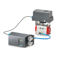
For linear valves, mount all hardware as shown in Figure 1.
To determine which holes on the mounting bracket to use, refer to Figures 2 & 3
and Table 2 or follow these steps:
1 Set the actuator at half travel.
2 Align the feedback loop (Key 5) and feedback arm (Key 4) so that they are
both horizontal, as shown in Figure 1.
3 The feedback loop (Key 5) should be compressing the spring on the feedback
arm assembly (Key 4) anywhere between 1/4” and 1/2”.
NOTE: In order to achieve proper spring compression it may be necessary to
fl ip the mounting bracket - connecting block (Key 2).
4 Depending on the actuator type, size, and travel, a different combination of
holes on the mounting bracket will have to be used for each application. The
top 5 rows of holes are used to mount to the actuator. The bottom 4 rows are
used to mount to the positioner. Choose the combination that best allows the
feedback arm (Key 4), and the feedback loop (Key 5) to be horizontal and
parallel at half travel.
5 Once this arrangement is set, tighten all the fasteners.
6 Follow start-up as described in this handbook or in the Chapter on
“Commissioning” of the Siemens SIPART PS2 Operating Instructions (Latest
Edition).
OLD LINEAR MOUNTING INSTRUCTIONS
3