EasyManuals Logo

Siemens PXC Modular Series User Manual

Siemens PXC Modular Series
100 pages
To Next Page IconTo Next Page
To Previous Page IconTo Previous Page
Page #17 background imageLoading...
Page #17 background image
Compact Series Product Overview
36-Point Compact Series Product Diagram
17 |
100
Technical Reference Manual
145-172
Restricted
2018-09-25
36-Point Compact Series Product Diagram
PXC-36 Features, Symbols, and Status LEDs.
Terminal Block Connection
Label
Indicates
1
24V
~
Supply voltage, 24 Vac input.
2
System neutral.
3
Functional earth.
4 through 27
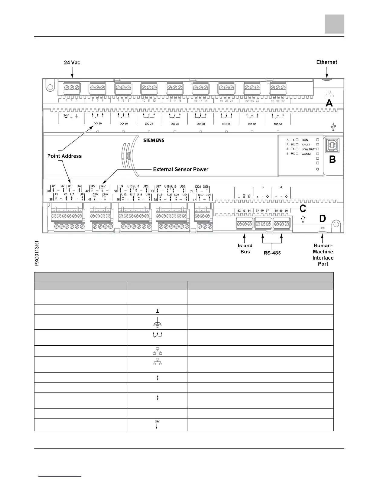
Digital Output relay, Normally Closed (NC), Common (C), Normally
Open (NO).
A
10B/100B Ethernet port.
B
USB Device port. Supports a generic serial interface for an HMI or
Tool connection. Does not support firmware flash upgrades.
30, 32, 33, 35, 36, 38
Super Universal (+). (X1 through X6)
31, 34, 37
Signal Common.
39, 41, 50, 52, 53, 55, 56, 58, 59, 61, 62,
64, 65, 67, 68, 70, 71, 73
Universal Input/Output (+). (U7 through U24)
40, 51, 54, 57, 60, 63, 66, 69, 72
Signal Common.
42, 44, 46, 48
24 Vdc external sensor power (+) source.

Table of Contents

Other manuals for Siemens PXC Modular Series

Questions and Answers:

Question and Answer IconNeed help?

Do you have a question about the Siemens PXC Modular Series and is the answer not in the manual?

Siemens PXC Modular Series Specifications

General IconGeneral
BrandSiemens
ModelPXC Modular Series
CategoryControl Unit
LanguageEnglish

Related product manuals