14 / 42
Siemens RDG100…/RDG110…/RDG140.../RDG160… Basic Documentation CE1P3182en
Building Technologies Functions 28 May 2009
4.6 Additional features
The output signals DC 0…10V can be inverted by means of DIP switch 4
(see section 4.7.3).
T
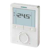
o ensure a minimum or maximum supply air volume, the output signal for the air
flow (DC 0...10V or 3-position) can be limited to a minimum value via parameter
P63 and to a maximum value via parameter P64.
Both values can be set between 0% and 100%.
T Room temperature
Y10 Control output
w Room temperature setpoint
XpH Proportional band Heating
XpC Proportional band Cooling
Vmin Minimum limitation air flow
max
min
Changeover
XpH
Y10
0%
100%
TR [°C]
XpC
W
C
H
Vmin
Vmax
Vmax Maximum limitation air flow
If Vmin is not set >0, then a minimum air flow of Vmin is assured in Comfort and
Energy Saving modes. In Protected mode, Vmin is 0.
Comfort or Energy Saving mode with Vmin Protection mode (Vmin = 0)
max
min
Y
0%
100%
TR [°C]
YV
CH
Vmin
Vmax
SpH
Comf/Eco
SpC
Comf/Eco
max
min
Y
0%
100%
TR [°C]
YV
C
H
Vmin
Vmax
SpH
Prot
SpC
Prot
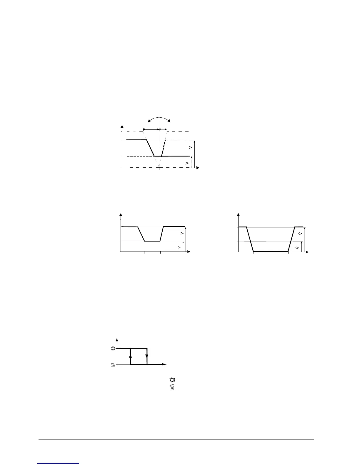
The water temperature acquired by the changeover sensor (QAH11.1 + ARG86.3)
is used to change over from heating to cooling mode and vice-versa. When the
water temperature is above 28 °C (parameter P37), the thermostat changes over to
heating mode, and to cooling mode when below 16 °C (parameter P36).
If the water temperature is between the 2 changeover points immediately after
power-up, the thermostat starts in heating mode.
The water temperature is acquired at 30-second intervals and the operating state is
updated accordingly.
16
M
T
w
[°C]
28
M Operating mode
Cooling mode
T
w
Water temperature
Heating mode
The QAH11.1 cable temperature sensor for automatic heating/cooling changeover
can be replaced by an external switch for manual, remote changeover:
Output signal inversion
Min / Max air flow
Automatic H/C
changeover
Remote heating/
cooling changeover
 Loading...