21 / 42
Siemens RDG100, RDG100T, RDG110, RDG140, RDG160 Basic Documentation CE1P3182en
Building Technologies Functions 28 May 2009
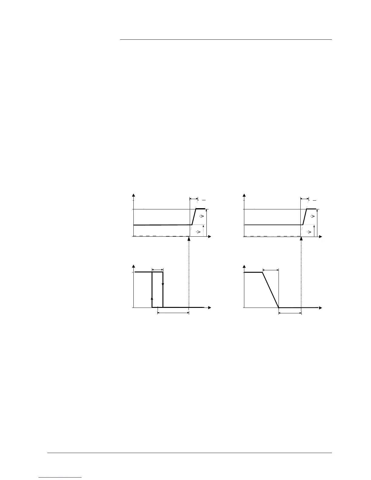
4.7.6 Single duct with radiator or floor heating
In single duct applications with radiator or floor heating, the thermostat controls a
valve plus an auxiliary electrical heater. Parameter P01 is not available.
The output signal for the air flow can be limited to a minimum and maximum value
if required (see section 4.6 "additional features").
The air flo
w starts to rise when the acquired room temperature is above "setpoint"
+ "dead zone".
The radiator receives an ON command when the acquired room temperature drops
below “setpoint” – “dead zone” (= “setpoint for radiator”).
Note: “Setpoint for radiator” is limited by parameter “Maximum heating setpoint”
(P10).
The radiator sequence can also be used for floor heating.
The "Floor heating limitation function" is described on page 15.
ON/OFF r
adiator / floor heating Modulating radiator / floor heating
Y
YR
TR [°C]
dz
max
min
Y
0%
100%
TR [°C]
XpC
YV
C
Vmin
Vmax
ON
OFF
W
SDH
Y
0%
100%
YR
TR [°C]
XpH
W
dz
max
min
Y
0%
100%
TR [°C]
XpC
YV
C
Vmin
Vmax
Y Output signal
TR Room temperature
W Effective setpoint Comfort
H Heating sequence
C Cooling sequence
YV Volume flow rate
YR Radiator / floor heating
XpH Proportional band heating
XpC Proportional band cooling
Vmin Minimum volume output
Vmax Maximum volume output
Note: The diagrams show the PI controller's proportional part only.
Setting the sequence and the control outputs
Refer to sections 4.5 (applications), 4.7.1 (sequences) and 4.7.3 (outputs).
Floor h
eating
Sequences
 Loading...