36 / 42
Siemens RDG100…/RDG110…/RDG140.../RDG160… Basic Documentation CE1P3182en
Building Technologies Engineering 28 May 2009
6.2 Connection diagrams
For details concerning connection of peripheral devices and setting of the DIP
switches please refer to the mounting instructions, document M3182.
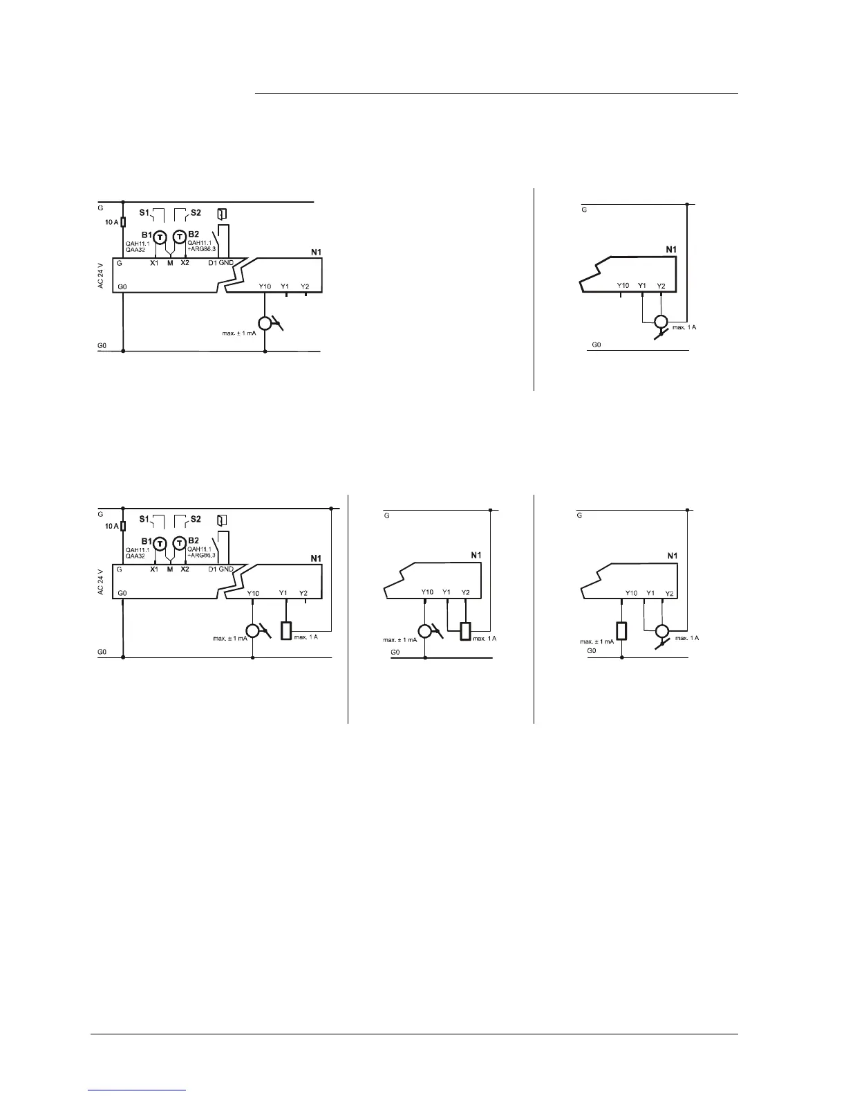
Application: Single-duct
1
V1 DC 0…10 V damper actuator V1 3-position damper actuator
N1 Room thermostat RDG400
S1..S3 Switch (keycard, window contact, etc.)
B1, B2 Temperature sensor (return air temperature, external room temperature, changeover sensor, etc.)
Application: Single-duct with electrical heater, radiator or heating / cooling
1
V1 DC 0…10 V damper actuator
V2 2-position or PWM electrical heater, radiator
or heating / cooling valve
V1 DC 0…10 V damper actuator
V2 3-position electrical heater,
radiator or heating / cooling
valve
V1 3-position damper actuator
V2 DC 0…10 V electrical heater,
radiator or heating / cooling valve
N1 Room thermostat RDG400
S1..S3 Switch (keycard, window contact, etc.)
B1, B2 Temperature sensor (return air temperature, external room temperature, changeover sensor, etc.)
Note
 Loading...