Electrical installation
• Ensure that the local regulations for electrical installa-
tions are complied with
• The connecting terminals are located under the flexi-
ble plastic cover
• Make wiring according to the plant documentation. If
not available, use the connection diagrams contained
in these Installation Instructions
• Observe the permissible cable lengths
• Switch on power only when commissioning the con-
troller
Settings
3337P01
3 4 5
1
2
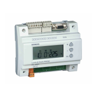
1 LED for test mode / fault / normal operation
2 DIP switch block
3 Setting slider for minimum charging temperature
4 Potentiometer for loading temperature (40…90 °C)
5 Potentiometer for maximum temperature (40…130 °C)
Switching differential:
Where? What?
1 2
Switching differential = 8 K
DIP switch block,
switches no. 1 and 2
Switching differential = 1 K
Switching differential = 4 K
Switching differential = 2 K
Operating mode (B2):
3
With minimum charging temperature
DIP switch block,
switch no. 3
Without minimum charging temperature
Application type (B3):
4 5
Applications 6, 7 2 Exchangers (∆t)
DIP switch block,
switches no. 4 and 5
Application 5 2 Collectors (∆t)
Applications 3, 4
Bypass (°C)
Applications 1, 2
Standard
Test mode:
6
Test mode
DIP switch block,
switch no. 6
Normal operation
Setpoint (1…30 K):
Temperature
setting slider
Temperature differential required between the two
plant elements
Minimum charging temperature (30…80 °C):
Setting slider 3 When switch no. 3 is set to
Absolute (load) temperature (40…90 °C):
Potentiometer 4
Switches no. 4 and 5 are set to
or
Maximum temperature (40…130 °C):
Potentiometer 5
Switches no. 4 and 5 are set to
Indication of operating state
The red LED indicates the controller’s operating state:
• LED lit: Mains voltage present (normal operation)
• LED flashes fast (4 Hz): In test mode
• LED flashes slow (1 Hz): Fault (B2)
The LED is also visible when the cover is fitted.
Commissioning
1. Remove housing cover.
2. Lift flexible plastic cover so that you can access the
setting elements.
3. Make the settings:
− Switching differential (switches no. 1 and 2)
− Operating mode (with / without minimum charging
temperature, switch no. 3)
− Application type (switches no. 4 and 5)
− Test mode (switch no. 6 = ON)
4. Replace flexible plastic cover.
5. Switch power on. LED for the operating state must
flash (test mode).
6. Move temperature setting slider to the minimum
value (<5 K) to prove contact Q1–Q3
► If response is wrong, refer to “Troubleshooting”
7. Move temperature setting slider to the maximum
value (>25 K) to prove contact Q4–Q6.
► If response is wrong, refer to “Troubleshooting”
8. Switch power off.
9. Switch controller back to normal operation (set
switch no. 6 to
OFF).
10. Switch power on. LED for the operating state must
light up (normal operation).
11. If a remote setting unit is used, set the controller’s
temperature setting slider to EXT.
12. First, set temperature setting slider to the minimum
value, then to the maximum value: Observe the con-
trol. The response may neither be too fast nor too
slow.
► If response is wrong, refer to “Troubleshooting”
13. Adjust the setpoint with the temperature setting
slider.
14. Replace housing cover.
Troubleshooting
Wrong response Possible causes
Regulating units do not
respond
• Regulating units not con-
nected
• No power supply
Regulating units travel
in the wrong direction
• Controller terminals incor-
rectly wired
• Controller and external sen-
sor mixed up
• Sensor not connected
Regulating units re-
main in one of their end
positions
• Temperature setting slider is
set to EXT and there is no
remote setting unit con-
nected
• External sensor not con-
nected or short-circuit
Control response too
slow
• Reduce switching differential
Control is unstable
• Increase switching differen-
tial
Siemens Switzerland Ltd / HVAC Products CE1G3337xx 23.11.2004 3/16
 Loading...