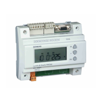
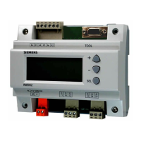
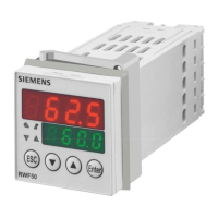
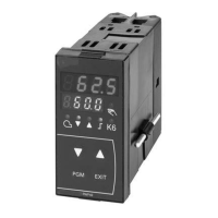
RWD62U Controller Installation and Commissioning Guide Document Number 129-410
October 1, 2004
Siemens Building Technologies, Inc. Page 3 of 10
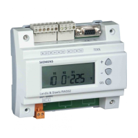
Display Explanation
Symbol
Description
Setting Range
Symbol Description Setting Range
Main Screen
Adjustable setting screen
TOOL PC communication port
being used
#
10 Application Numbers 10 through 59 (Not
consecutive numbers)
OUT RANGE The setting is out of range
Daytime operation
Err Sensor error
e
Night time operation
#10* * = Using, not the defaulted
sensor
X1 Universal (Main) Input X1
Siemens Ni 1000 Ω: -58°F
to 302°F (-50°C to 150°C)
(unchangeable)
Pt 1000 Ω: -4° to 356°F-
(20°C to 180°C)
(unchangeable)
0 to 10Vdc: -100 to 8,000
WIN/SUM
Winter/Summer mode being
chosen or activated
X2 Universal (Auxiliary) Input
X2
Siemens Ni 1000 Ω: -58°F
to 302°F (50°C to 150°C)
(unchangeable)
Pt 1000 Ω: -4° to 356°F-
(-20°C to 180°C)
(unchangeable)
0 to 10Vdc: -100 to 8,000
Variable resistor: the
resistance range should be
within 0 to 1000 ohm
LIM
Limiter mode being chosen or
activated
---- No unit (e.g. pressure, air
quality and air volume flow)
REM
Remote setpoint mode being
chosen or activated
Sec Second
CAS
Cascade mode being chosen
or activated
Y1 Analog output 1 0 to 10 Vdc
MaxPrior
Maximum priority mode being
chosen or activated
Y2 Analog output 2 0 to 10 Vdc
SP-1 Setpoint 1
°C Celsius scale
SP-2 Setpoint 2
°F Fahrenheit scale
SP-h
Setpoint on the heating side
for temperature control
K Kelvin
SP-c Setpoint on the cooling side
for temperature control
% Percentage scale
XDZ
For H + C application. Dead
zone between H and C day
setpoints when in REM
mode.
Ni: 0.5 to 180 K
Pt: 0.5 to 180 K
Active input: 0.05 to 7,300
Commissioning Screen
PS1 Parameter setting
mode: Application No.
set-up
PS4 Parameter setting mode:
Main control loop setting
PS2 Parameter setting
mode: Defining Unit X1
and X2
PS Next To enter the next
parameter setting
PS3 Parameter setting
mode: Auxiliary control
PS Exit To exit the whole
parameter setting mode
+
 Loading...
