88 / 100
Siemens Commissioning Guide CM1G5192en
Building Technologies 10 Parameterization 29.07.2010
Bit fields:
Bit00 Act. Freq. r0024 <= P1080 0 NO, 1 YES
Bit01 Act. freq. r0024 <= P2155 0 NO, 1 YES
Bit02 Act. freq. r0024 > P2155 0 NO, 1 YES
Bit03 Act. freq. r0024 > zero 0 NO, 1 YES
Bit04 Act. freq. r0024 >= setp. 0 NO, 1 YES
Bit05 Act. freq. r0024 <= P2167 0 NO, 1 YES
Bit06 Act. freq. r0024 >= P1082 0 NO, 1 YES
Bit07 Act. freq. r0024 == setp. 0 NO, 1 YES
Bit08 Reserved
Bit09 Act. unfilt. Vdc < 800 V 0 NO, 1 YES
Bit10 Act. unfilt. Vdc > 800 V 0 NO, 1 YES
Bit11 No load condition 0 NO, 1 YES
r2198 CO/BO: Monitoring word 2
Monitoring word 2, which indicates the state of monitor functions. Each bit represents one
monitor function.
Unit: - Min: - Def: - Max: -
Level 3
Bit fields:
Bit00 Reserved
Bit01 Reserved
Bit02 Reserved
Bit03 Reserved
Bit04 | n,set | < 3 Hz 0 NO, 1 YES
Bit05 n,set > 0 0 NO, 1 YES
Bit06 Motor blocked 0 NO, 1 YES
Bit07 Motor stalled 0 NO, 1 YES
Bit08 Reserved
Bit09 |T,act| > T,rated & setpoint reached 0 NO, 1 YES
Bit10 |T,act| > T,rated value 0 NO, 1 YES
Bit11 Belt failure warning 0 NO, 1 YES
Bit12 Belt failure trip 0 NO, 1 YES
Note: Bit12 (belt failure trip) will only be reset after fault quitting and applying a new ON command.
T, rated is calculated from the machine data during quick commissioning.
P2200[2] BI: Enable PID controller
The PID mode allows the user to enable / disable the PID controller. Setting to 1 enables the
PID controller.
Unit: - Min: 0:0 Def: 0:0 Max: 4000:0
Level 2
Index: P2200[0]: VSD in ”Auto” mode P2200[1]: VSD in ”Hand” mode
Dependency: Setting 1 does not disable the normal ramp times set in P1120 and P1121. However the normal frequency setpoints are
disabled. A PID setpoint change will be limited by P2257 and P2258 (PID setpoint ramp)
Following an OFF1 or OFF3 command, however, the VSD frequency will ramp down to zero using the ramp time set in
P1121 (P1135 for OFF3).
Note: The PID setpoint source is selected using P2253. The PID setpoint and the PID feedback signal are interpreted as [%]
values (not [Hz]). The output of the PID controller is displayed as [%] and then normalized into [Hz] through P2000
(reference frequency) when PID is enabled. In level 3, the PID controller source enable can also come from the digital
inputs in settings 722.0 to 722.2 for DIN1 to DIN3 or from any other BiCo source.
The minimum and maximum motor frequencies (P1080 and P1082) as well as the skip frequencies (P1091 to P1094)
remain active on the VSD output. However, enabling skip frequencies with PID control can produce instabilities.
P2201
through
P2215
Fixed PID setpoint 1 through 15
Defines fixed PID setpoint 1.
Unit: % Min: -200.00 Def: See note below Max: 200.00
Level 3
Details: Defines fixed PID setpoint 1. In addition, you can set any of the digital input parameters to fixed PID setpoint via the
digital inputs (P0701 - P0706).
There are 3 selection modes for the PID fixed setpoint:
1. Direct selection (P0701=15 or P0702=15, etc.)
In this mode of operation, 1 digital input selects one PID fixed setpoint
2. Direct selection with ON command (P0701=16 or P0702=16, etc.)
Description as for 1) except that this type of selection delivers an ON command concurrent with any setpoint selection.
3. Binary Coded Decimal selection with ON command (P0701 - P0704=17)
Using this method to select the PID fixed setpoint allows you to choose up to 16 different PID setpoints.
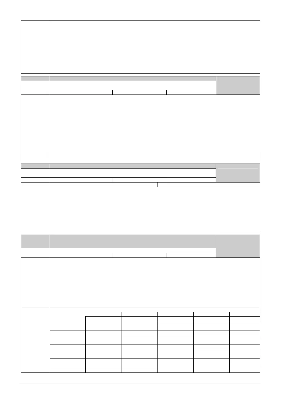
The setpoints are selected according to the following table:
Note: An ON command is only generated if all 6 digital inputs (P0701 - P0704) are set to 17.
DIN4 DIN3 DIN2 DIN1
OFF Inactive Inactive Inactive Inactive
P2201 FF1 Inactive Inactive Inactive Active
P2202 FF2 Inactive Inactive Active Inactive
P2203 FF3 Inactive Inactive Active Active
P2204 FF4 Inactive Active Inactive Inactive
P2205 FF5 Inactive Active Inactive Active
P2206 FF6 Inactive Active Active Inactive
P2207 FF7 Inactive Active Active Active
P2208 FF8 Active Inactive Inactive Inactive
P2209 FF9 Active Inactive Inactive Active
P2210 FF10 Active Inactive Active Inactive
P2211 FF11 Active Inactive Active Active
 Loading...


