SENTRON
SWITCHED ETHERNET PROFINET Module
7KM9300-0AE01-0AA0
Operating Instructions
English
2 Order No.: 3ZW1012-0KM03-0AA0
English
The products described here were developed to perform safety-oriented functions as
part of an overall installation or machine. A complete safety-oriented system gener-
ally features sensors, evaluation units, signaling units, and reliable shutdown con-
cepts. It is the responsibility of the manufacturer to ensure that a system or machine
is functioning properly as a whole. Siemens AG, its Regional Offices, and associated
companies (hereinafter referred to as "Siemens") cannot guarantee all the properties
of an overall installation or machine that has not been designed by Siemens.
Nor can Siemens assume liability for recommendations that appear or are implied in
the following description. No new guarantee, warranty, or liability claims beyond the
scope of the Siemens general terms of supply are to be derived or inferred from the
following description.
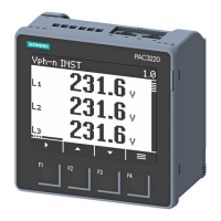
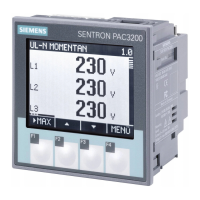
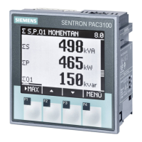
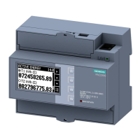
The SWITCHED ETHERNET PROFINET module is intended for use with PAC power
monitoring devices or COM800. The SWITCHED ETHERNET PROFINET module
integrates the PAC power monitoring device or COM800 in power management and
automation systems.
The SWITCHED ETHERNET PROFINET module
• provides the device's measured values for the PROFINET controller.
• links two Ethernet nodes via the Ethernet switch function (PROFINET IRT)
• supports Modbus TCP.
See Fig. 2.
Mounting position: vertical on the device
Mount the SWITCHED ETHERNET PROFINET module before commissioning the
device. Note the following:
• ESD guidelines
• The PROFINET guidelines for installation, grounding e. t. c. - PN-Installa-
tion-Guide:
http://www.profibus.com/nc/downloads/downloads/profinet-installation-guide/dis-
play/ ;
PN Cabling Guide:
http://www.profibus.com/nc/downloads/downloads/profinet-cabling-and-intercon-
nection-technology/display/
• Use of the module is only permitted in a LAN or a segment of the LAN if all con-
nected nodes are located within one building and are supplied via a power supply
network.
Hold the SWITCHED ETHERNET PROFINET module by the plastic enclosure only.
a) Ensure safe isolation from supply.
b) Discharge yourself.
c) Mount the device.
Installation steps see Fig. 4.
(1) Connect the SWITCHED ETHERNET PROFINET module to the device. The
guide and the anti-twist element help here.
(2) Plug the RJ 45 connectors into the RJ 45–sockets.
(3) Make sure the connectors have engaged.
(4) Provide sufficient mechanical strain relief for the Ethernet cable.
The SWITCHED ETHERNET PROFINET module is assigned to the
PROFINET controller using configuration software, such as STEP 7. You can find
the GSDML file required for this on the Internet (see Online Service). For COM800 the
settings can only be changed by configuration software or by using powerconfig..
For configuration details, please refer to the following manuals:
• "PROFIBUS DPV1, SWITCHED ETHERNET PROFINET Module"
• 3VA Communication Manual.
These two manuals can be found on the CD for the Device and on the Internet (see
Online Service).
Notice
Siemens offers IT security mechanisms for its automation and drive product portfolio
in order to support the safe operation of the plant/machine. Our products are also
continuously developed further with regard to IT security. We therefore recommend
that you keep yourself informed about updates and upgrades for our products and
always use the latest version of each product. You can find information on this at:
http://support.automation.siemens.com.
You can register for a product-specific newsletter here. For the safe operation of a
plant/machine, however, it is also necessary to integrate the automation components
into an overall IT security concept for the entire plant/machine, which corresponds to
the state-of-the-art IT technology. You can find information on this at:
http://www.siemens.com/industrialsecurity.
Products used from other manufacturers should also be taken into account here
Read and understand these instructions before installing,
operating, or maintaining the equiment.
DANGER
Hazardous voltage.
Will cause death or serious injury.
Turn off and lock out all power supplying this device
before working on this device.
CAUTION
Reliable functioning of the equipment is only ensured with
certified components.
Important note
Area of application
Tools required for installation
Installation and connection
Configuring
Fig. 4: Setting the language on the LCD of the SENTRON PAC
Fig. 5: Setting the IP-configuration of the module on the LCD of the device. You
can also make these settings in the STEP 7 configuration software or in
powerconfig.
Technical data
Industrial Ethernet:
Integral, IRT--enabled switch
with 2 x 8--pin RJ 45- sockets
10/100Mbit/s
Auto crossover
Auto negotiation
Power Supply Fromdevice
Electrical isolation between the
device and the Ethernet inter-
face of the SWITCHED
ETHERNET PROFINET module
AC 1500 V
Electrical isolation between the
Ethernet interface and the Ether-
net shield
AC 500 V
Type of protection IP20
Permissible degree of pollution 2 in accordance with IEC 61131
Weight approx. 36 g
Dimensions of the enclosure in
mm (HxWxD)
63 x 43 x 22
Overall depth of the SWITCH ETH-
ERNET PROFINET module in mm
in addition to the overall depth of
the device
22
Housing design VDT 3400 structure 36
Cable length at least CAT5, < 100 m;
you can find further information at:
http://www.profibus.com/nc/downloads/downloads/
profinet-cabling-and-interconnection-technology/dis-
play/
Tolerances in accordance with DIN 16901:1982–11
Cooling Passive air cooling in the form of ventilation slots
Flammability class V–0
Security information
 Loading...
