Supplements to ET 200SP documentation
2.5 I/O module manuals
Product information on the documentation of the ET 200SP distributed I/O system
56 Product Information, 02/2021, A5E03799595-BG
If you use the user-data mapping via data record DS 130, note that the texts for the measured
variables are also displayed incorrectly during configuration.
During configuration of the measured variables for the total active, reactive, and apparent
power, select the following texts:
Desired measured variable for the user-data
Text to select during configuration
Total active power L1L2L3
Total apparent power L1L2L3 (ID00034)
Total reactive power L1L2L3
Total active power L1L2L3 (ID00035)
Total apparent power L1L2L3
Total reactive power L1L2L3 (ID00036)
Max. total apparent power (ID00065)
Max. total reactive power
Max. total active power (ID00066)
Max. total apparent power
Max. total reactive power (ID00067)
Min. total apparent power (ID00095)
Min. total reactive power
Min. total active power (ID00096)
Min. total apparent power
Min. total reactive power (ID00097)
The project configuration modification described above is no longer required if the following
tools and GSD files are used:
• STEP 7 (TIA Portal) as of V14
• STEP 7 V5.5 SP4 or higher with HSP 0227
• GSD file GSDML-V2.32-ET200SP-20160706
Manual AQ 2xU/I HF, Edition 02/2014
Section 3.1 "Wiring and block diagram, pin assignment"
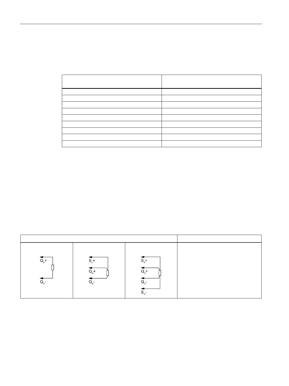
You can now also use the 3-wire connection in addition to the 2-wire and 4-wire connection
for the analog module AQ 2xU/I HF.
Pin assignment for AQ 2xU/I HF
tion
tion
tion
• Qn+: Analog output voltage/current
(positive), channel n
• Qn-: Analog output voltage/current
(negative), channel n
• Sn+: Sensor line positive, channel n
• S
n-: Sensor line negative, channel n
The 3-wire connection and 4-wire connection make compensation for line impedance
possible. The compensation is not possible for 2-wire connections due to the missing sensor
cable.

 Loading...


