12-6
Operator Panel OP3
Edition 11/99
12.3.1 Control and Response Bits
Three bytes are present in the interface area for the control and response
bytes. Bytes n+0 and n+1 are used to synchronize the OP3 and the S7. Byte
n+3 is not applicable to the OP3.
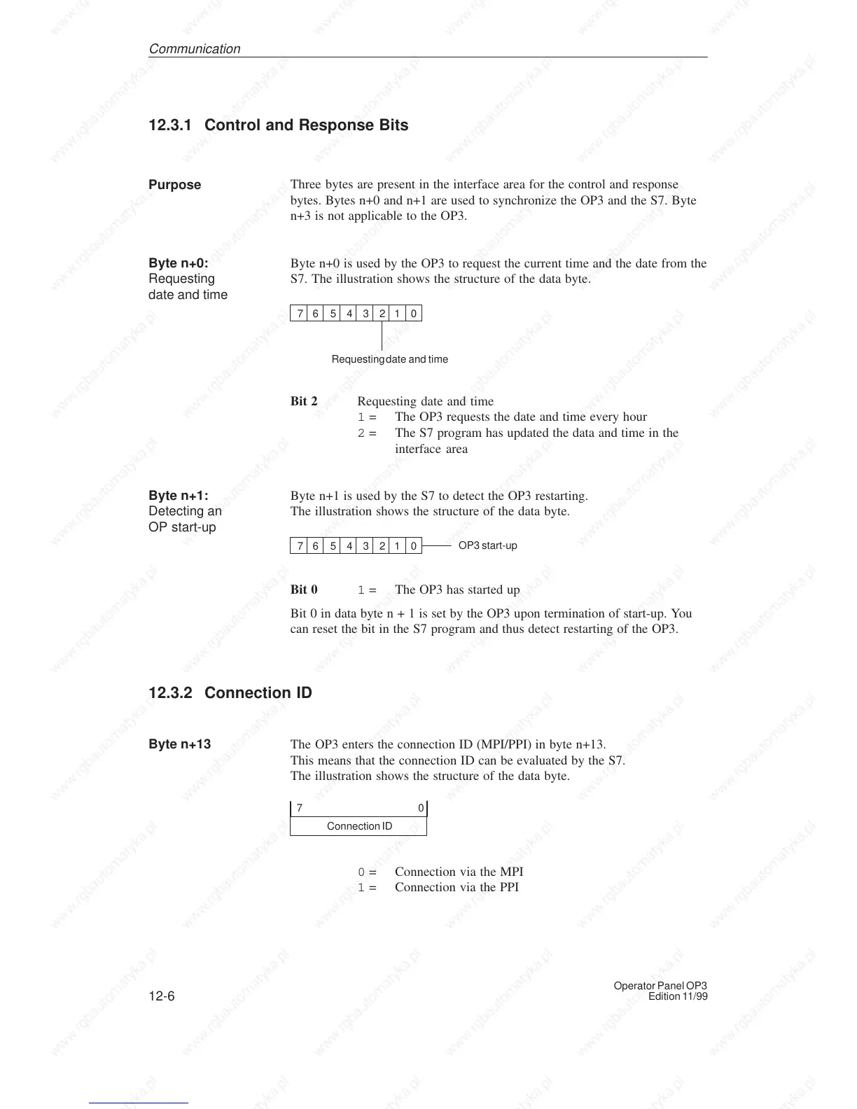
Byte n+0 is used by the OP3 to request the current time and the date from the
S7. The illustration shows the structure of the data byte.
7 6 5 4 3 2 1 0
Requesting date and time
Bit 2 Requesting date and time
1 = The OP3 requests the date and time every hour
2 = The S7 program has updated the data and time in the
interface area
Byte n+1 is used by the S7 to detect the OP3 restarting.
The illustration shows the structure of the data byte.
7 6 5 4 3 2 1 0
OP3 start-up
Bit 0 1 = The OP3 has started up
Bit 0 in data byte n + 1 is set by the OP3 upon termination of start-up. You
can reset the bit in the S7 program and thus detect restarting of the OP3.
12.3.2 Connection ID
The OP3 enters the connection ID (MPI/PPI) in byte n+13.
This means that the connection ID can be evaluated by the S7.
The illustration shows the structure of the data byte.
Connection ID
0
7
0 = Connection via the MPI
1 = Connection via the PPI
Purpose
Byte n+0:
Requesting
date and time
Byte n+1:
Detecting an
OP start-up
Byte n+13
Communication