15-3
Operator Panel OP3
Edition 11/99
Note
If you require the hardware test (refer to Section 16) to test the RS232 inter-
face, connect pins 3 and 4 to the 9-pin subminiature D connector of the serial
transfer cable.
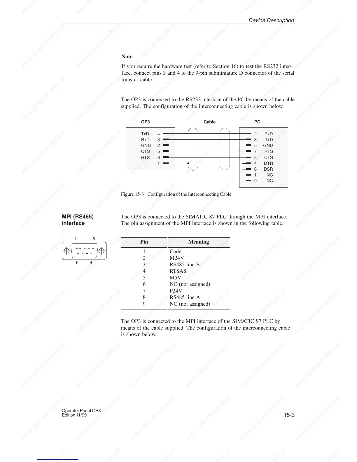
The OP3 is connected to the RS232 interface of the PC by means of the cable
supplied. The configuration of the interconnecting cable is shown below.
OP3
TxD 4
RxD 3
GND 2
CTS 5
RTS 6
1
PC
2 RxD
3 TxD
5 GND
7RTS
8 CTS
4 DTR
6 DSR
1NC
9NC
Cable
Figure 15-3 Configuration of the Interconnecting Cable
The OP3 is connected to the SIMATIC S7 PLC through the MPI interface.
The pin assignment of the MPI interface is shown in the following table.
Pin Meaning
1
2
3
4
5
6
7
8
9
Code
M24V
RS485 line B
RTSAS
M5V
NC (not assigned)
P24V
RS485 line A
NC (not assigned)
The OP3 is connected to the MPI interface of the SIMATIC S7 PLC by
means of the cable supplied. The configuration of the interconnecting cable
is shown below.
MPI (RS485)
interface
Device Description
15
69