RF300 system planning
4.1 Fundamentals of application planning
SIMATIC RF300
4-2 System Manual, Release 04/2006, J31069 D0166-U001-A2-7618
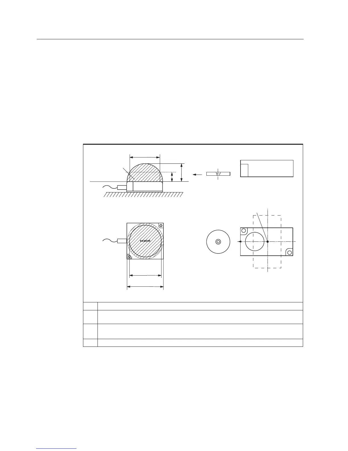
4.1.2 Transmission window and read/write distance
The reader generates an inductive alternating field. The field is strongest near to the reader.
The strength of the field decreases in proportion to the distance from the reader. The
distribution of the field depends on the structure and geometry of the antennas in the reader
and transponder.
A prerequisite for the function of the transponder is a minimum field strength at the
transponder achieved at a distance S
g
from the reader. The picture below shows the
transmission window between transponder and reader:
Table 4-1 Reader and ANT1 transmission window and read/write distance
3ODQYLHZ
7UDQVPLVVLRQ
ZLQGRZ
5HDGHUV
6
J
6
D
/
'
6LGHYLHZ
7UDQVSRQGHU
/6DPD[ /G
/6DPLQ /PD[
6,(0(16
6,0$7,&
5)7
7UDQVSRQGHU
63
5)7
S
a
: Operating distance between transponder and reader
S
g
Limit distance (maximum clear distance between upper surface of the reader and the
transponder, at which the transmission can still function under normal conditions)
L Length of a transmission window
The length L
D
is valid for the calculation. At S
a,min
, the field length increases from L
D
to L
max
.
SP Intersection of the axes of symmetry of the transponder