RF300 system planning
4.1 Fundamentals of application planning
SIMATIC RF300
4-4 System Manual, Release 04/2006, J31069 D0166-U001-A2-7618
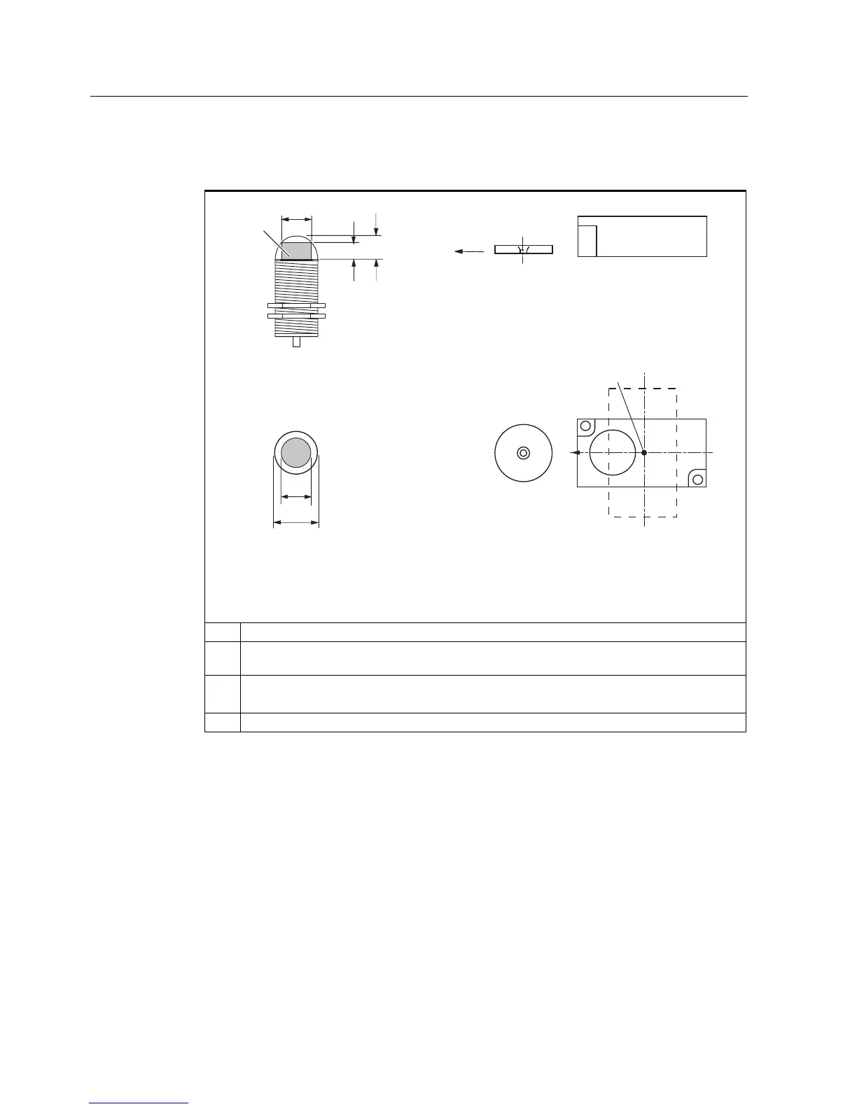
Table 4-3 ANT18 and ANT30 transmission window and read/write distance
6LGHYLHZ
7UDQVSRQGHU
6,(0(16
6,0$7,&
5)7
7UDQVSRQGHU
63
5)7
3ODQYLHZ
7UDQVPLVVLRQ
ZLQGRZ
6
J
6
D
/
G
/6
DPD[
/
G
/6
DPLQ
/
PD[
S
a
: Operating distance between transponder and reader
S
g
Limit distance (maximum clear distance between upper surface of the reader and the
transponder, at which the transmission can still function under normal conditions)
L Diameter of a transmission window
The length L
d
is valid for the calculation. At S
a,min
, the field length increases from L
d
to L
max
.
SP Intersection of the axes of symmetry of the transponder
The active field for the transponder consists of a circle (cf. plan view).
The transponder can be used as soon as the intersection (SP) of the transponder enters the
circle of the transmission window.
From the diagrams above, it can also be seen that operation is possible within the area
between S
a
and S
g
. The active operating area reduces as the distance increases, and
shrinks to a single point at distance S
g
. Only static mode should thus be used in the area
between S
a
and S
g
.