Analog Input Module AI 8xU/R/RTD/TC HF (6ES7531-7PF00-0AB0)
Manual, 09/2016, A5E36647959-AB
19
This section contains the block diagram of the module and outlines various connection
options.
You can find information on wiring the front connector, creating a cable shield, etc. in the
Wiring section of the S7-1500/ET 200MP
(http://support.automation.siemens.com/WW/view/en/59191792) system manual.
You can find additional information on compensating the reference junction temperature in
the function manual Analog value processing
(http://support.automation.siemens.com/WW/view/en/67989094), the structure of a data
record in the section Structure of the data record for dynamic reference temperature
(Page 66).
You may use and combine the different wiring options for all channels.
Do not insert the potential jumpers included with the front connector!
Meaning of the abbreviations used in the following figures:
Voltage input channel n (voltage only)
Measuring input channel n
Current output for RTD, channel n
Supply voltage connection
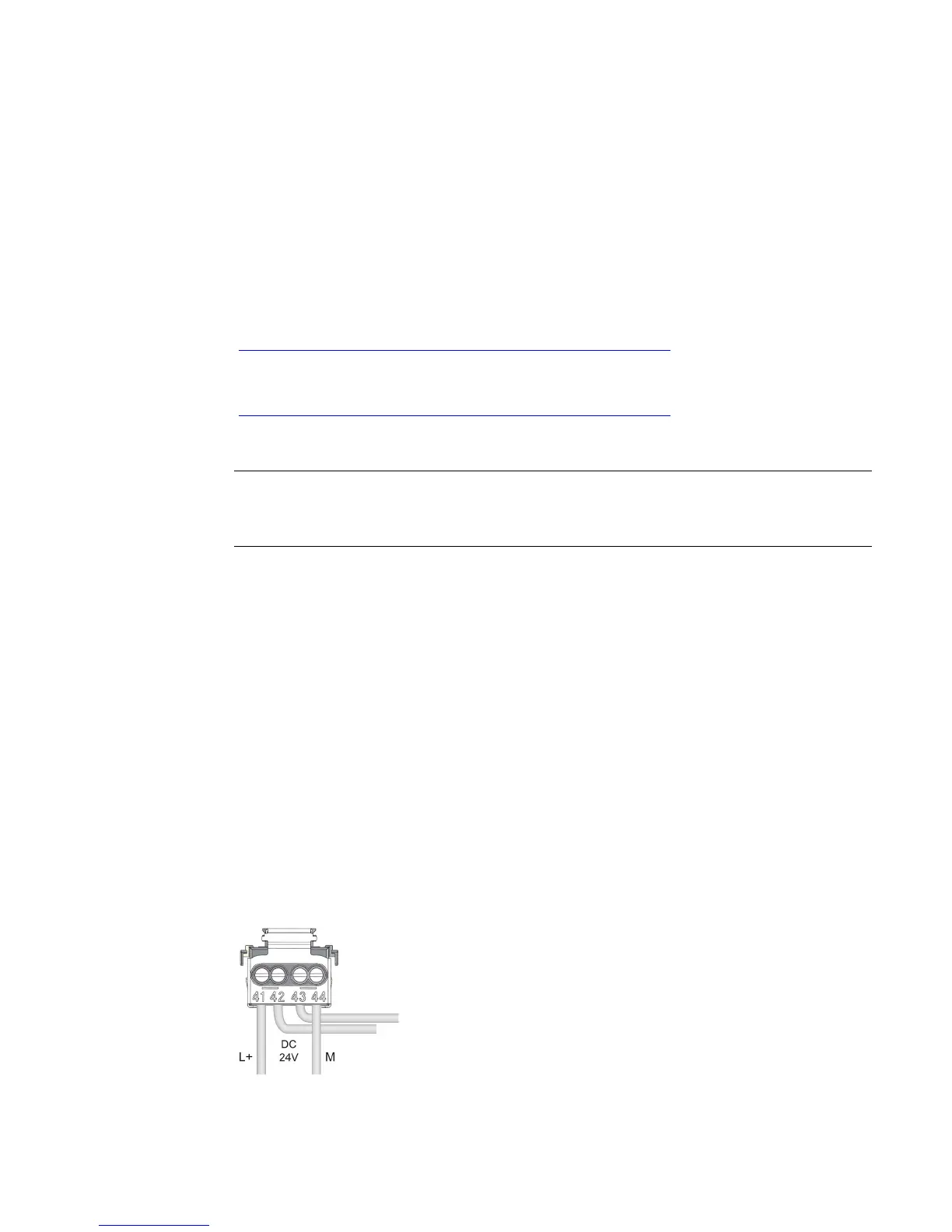
Pin assignment for the power supply element
The power supply element is plugged onto the front connector for powering the analog
module. Wire the supply voltage to terminals 41 (L+) and 44 (M). You can use terminals 42
(L+) and 43 (M) to loop the potential to the next module.
Figure 3-1 Power supply element wiring
 Loading...


