EasyManuals Logo

Siemens SIMATIC S7-1500T User Manual

Siemens SIMATIC S7-1500T
83 pages
To Next Page IconTo Next Page
To Previous Page IconTo Previous Page
Page #21 background imageLoading...
Page #21 background image
Wiring
Analog Input Module AI 8xU/R/RTD/TC HF (6ES7531-7PF00-0AB0)
Manual, 09/2016, A5E36647959-AB
21
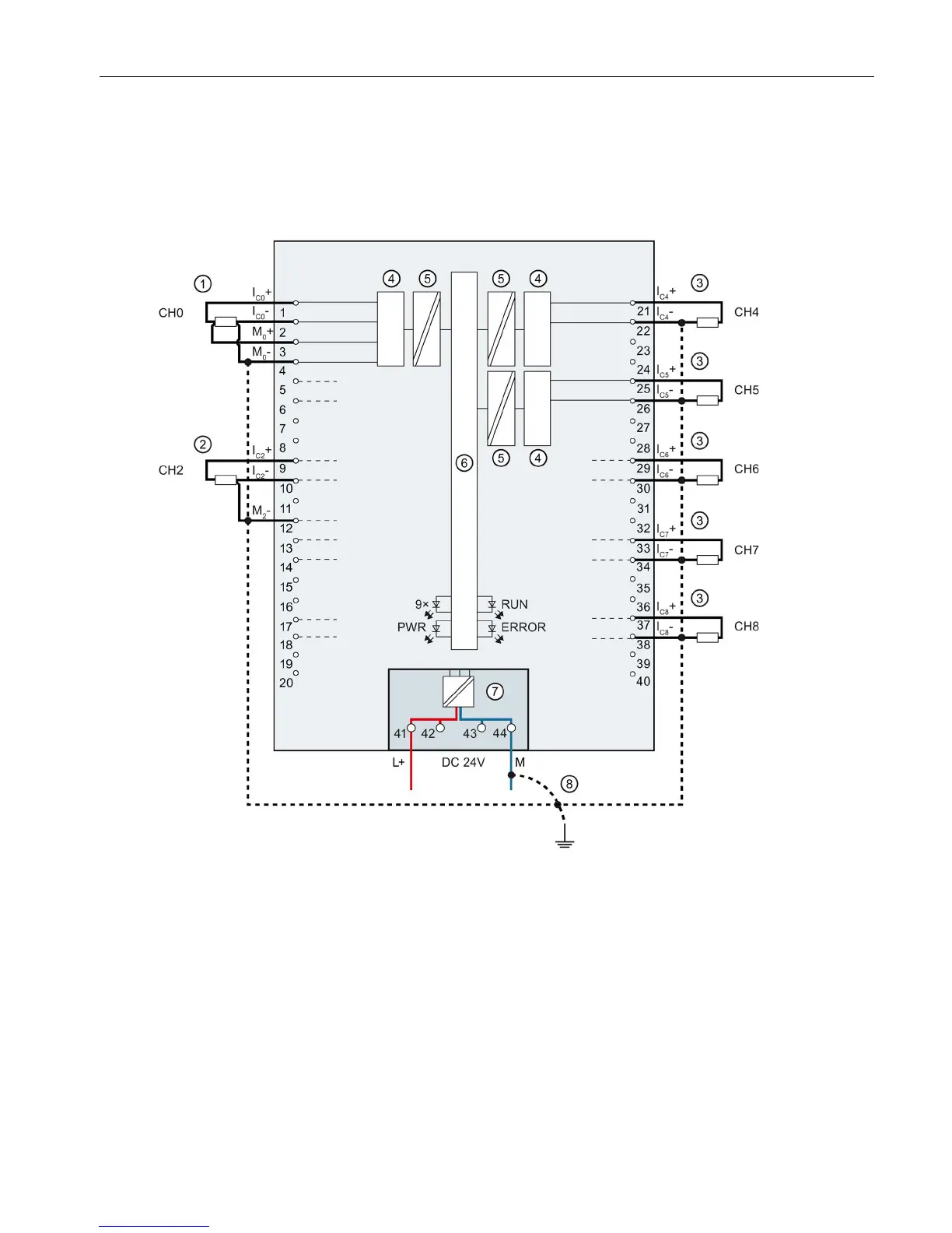
Connection: 2, 3 and 4-wire connection of resistance-type transmitters or resistance thermometers
(RTD)
The example in the following figure shows the pin assignment for 2, 3 and 4-wire
connections of resistance-type transmitters or resistance thermometers.
4-wire connection CHx Channel or 9 x channel status
(green/red)
3-wire connection
RUN
Status display LED (green)
2-wire connection
ERROR
Error display LED (red)
Analog-to-Digital Converter (ADC)
PWR
LED for power supply (green)
Electrical isolation
Backplane bus interface
Supply voltage via power supply element
Equipotential bonding cable (optional)
Figure 3-3 Block diagram and terminal assignment for 2, 3, and 4-wire connection

Other manuals for Siemens SIMATIC S7-1500T

Questions and Answers:

Question and Answer IconNeed help?

Do you have a question about the Siemens SIMATIC S7-1500T and is the answer not in the manual?

Siemens SIMATIC S7-1500T Specifications

General IconGeneral
BrandSiemens
ModelSIMATIC S7-1500T
CategoryController
LanguageEnglish

Related product manuals