Technical specifications
Analog Input Module AI 8xU/R/RTD/TC HF (6ES7531-7PF00-0AB0)
52 Manual, 09/2016, A5E36647959-AB
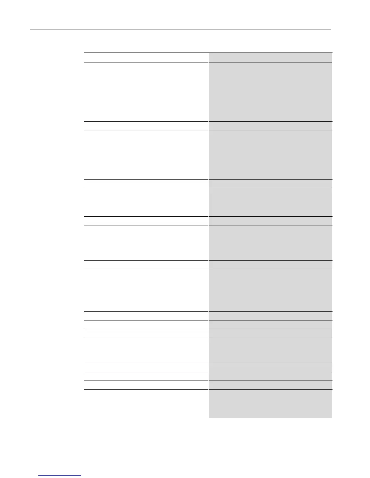
Diagnostics indicator LED
Monitoring of supply voltage (PWR LED)
Electrical isolation of channels
Between the channels, in groups of
Between the channels and backplane bus
Between the channels and power supply of the
electronics
Permitted potential difference
Between different circuits
60 V DC / 30 V AC; Isolation measured for 120 V
AC basic isolation: Between the channels and
supply voltage L+, between the channels and the
backplane bus, between the channels
2000 V DC between the channels and the supply
voltage L+, 2000 V DC between the channels and
the backplane bus, 2000 V DC between the
channels, 707 V DC (type test) between the sup-
ply voltage L+ and the backplane bus
Ambient temperature during operation
Horizontal mounting position, min.
Horizontal mounting position, max.
Vertical mounting position, min.
Vertical mounting position, max.
Cable compensation is performed alternately to
measurement with the R/RTD three-wire meas-
u
rement. Two module cycles are thus required for
a measured value.
 Loading...


