Fail-Safe Electronic Modules
8.2 4 /8 F-DI/4 F-DO DC24V/2A PROFIsafe Digital Electronic Module
ET 200pro Distributed I/O System - Fail-Safe Modules
Operating Instructions, 05/2007, A5E00394073-02
105
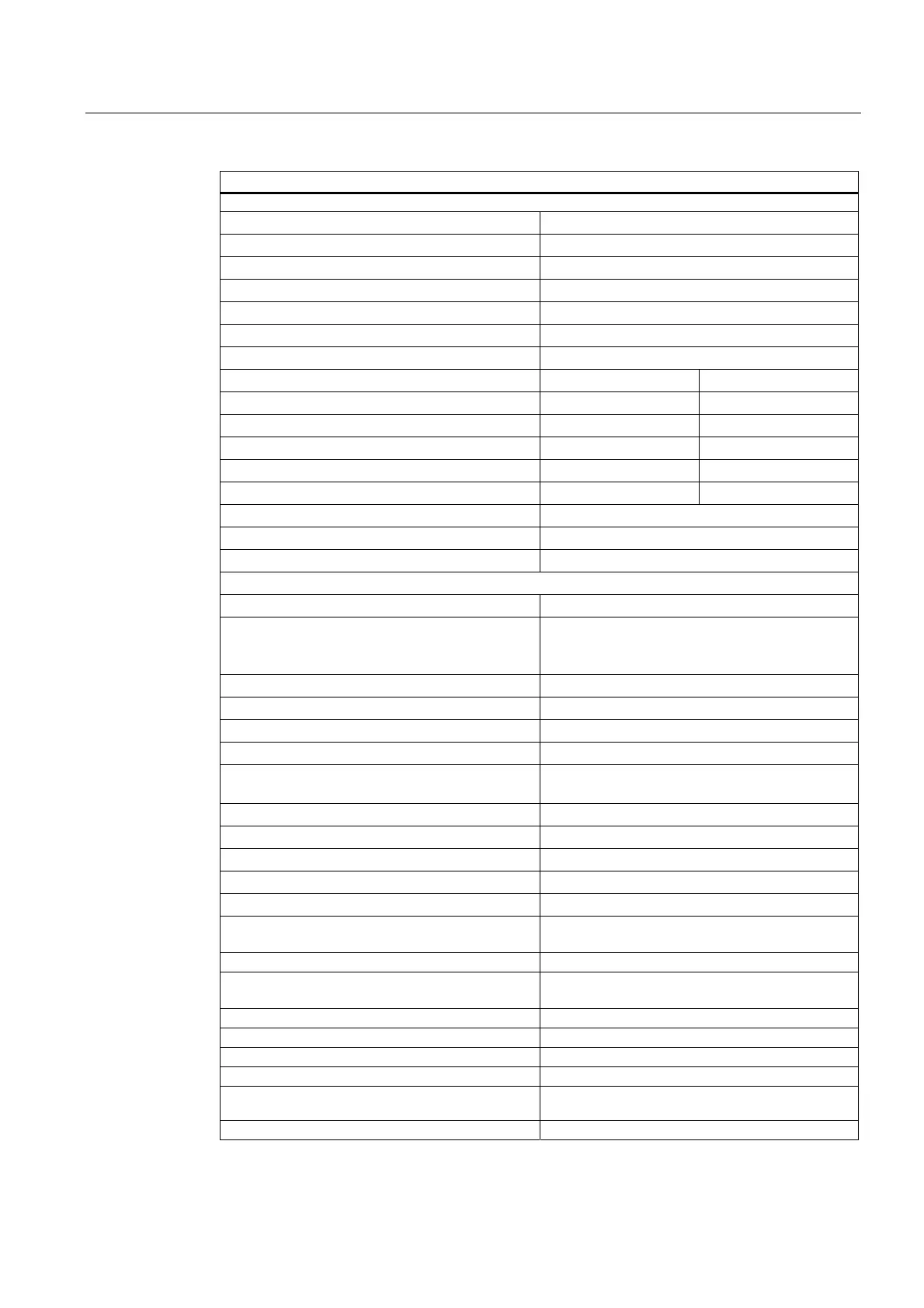
Technical Specifications
Data for Selecting a Sensor **
• Input voltage
• Rated value
24 V DC
• "1" signal
15 V to 30 V
• "0" signal
-30 V to 5 V
Input current
• "1" signal
Typ. 3.7 mA
Input delay Assignable (for all inputs together)
• For "0" after "1"
Typ. 0.5 ms (0.3 ms to 0.7 ms)
Typ. 3 ms (2.6 ms to 3.4 ms)
Typ. 15 ms (13 ms to 17 ms)
• For "1" after "0"
Typ. 0.5 ms (0.3 ms to 0.7 ms)
Typ. 3 ms (2.6 ms to 3.4 ms)
Typ. 15 ms (13 ms to 17 ms)
Input characteristic In accordance with IEC 61131-2, Type 1
Connection of 2-wire BERO Not possible
• Permissible quiescent current
Max. 0.6 mA
Data for Selecting an Actuator**
Output voltage
• "1" signal • Min. L+ (-1.5 V)
• P-switch: L+ (-1.5 V), minimum; voltage drop
at M-switch: 0.5 V, maximum
Output current for "1" signal
• Rated value
2 A
• Permissible range
20 mA to 2.4 A
For "0" signal (residual current) Max. 0.5 mA
Indirect control of load by means of coupling
relay:
For "0" signal (residual current)
• P-switch
Max. 0.5 mA
• M-switch
Max. 1 mA
Load resistance range 12 Ω to 1 kΩ
Lamp load Max. 10 W
Wire break monitoring (open load detection) and
overload monitoring
• Response threshold
I < 4 to 19 mA
• Fault detection time
Depends on the assigned readback time (see
"Response Times"
)
Parallel switching of 2 outputs Not possible
Control of a digital input Not possible
Switching frequency
• With resistive load
Max. 30 Hz
• With inductive load in accordance with IEC
60947-5-1, DC13
Max. 0.1 Hz
• With lamp load
Max. 10 Hz