Fail-Safe Electronic Modules
8.2 4 /8 F-DI/4 F-DO DC24V/2A PROFIsafe Digital Electronic Module
ET 200pro Distributed I/O System - Fail-Safe Modules
Operating Instructions, 05/2007, A5E00394073-02
97
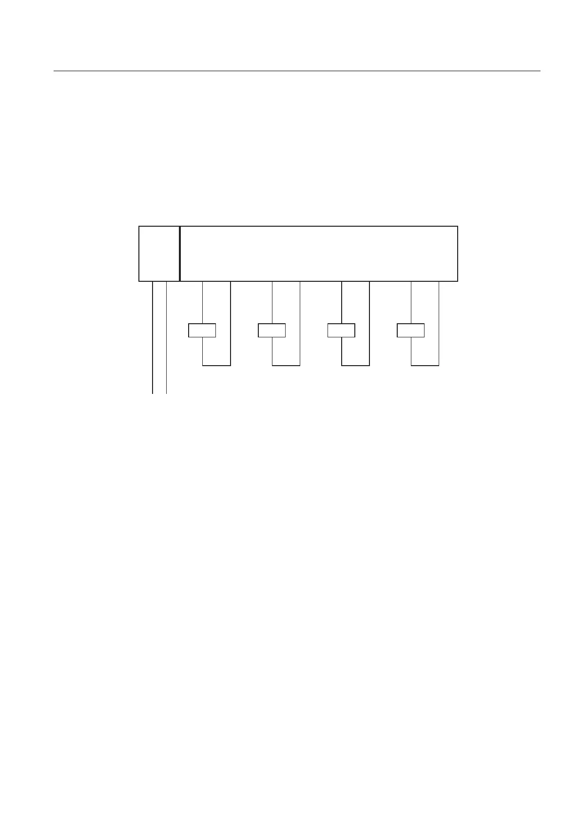
8.2.6 Wiring of Outputs of the 4/8 F-DI/4 F-DO DC24V/2A PROFIsafe Electronic Module
Use Case 1: Wiring a Load to Each Digital Output
Each of the four fail-safe digital outputs consists of one DOx P P-switch (current sourcing)
and one DOx M M-switch (current sinking). They connect the load between the P- and M-
switches. The two switches are always controlled so that voltage is applied to the load.
The wiring is carried out at the connection module.
2L+ M
L+ M
DO0
(M0)
DO0
(P0)
DO1
(M1)
DO1
(P1)
K0 K1
DO2
(M2)
DO2
(P2)
K2
DO3
(M3)
DO3
(P3)
K3
4/8 F-DI/4 F-DO
2L+
Figure 8-18 Wiring Diagram for the 4/8 F-DI/4 F-DO DC24V/2A PROFIsafe Electronic Module