Fail-Safe Electronic Modules
8.2 4 /8 F-DI/4 F-DO DC24V/2A PROFIsafe Digital Electronic Module
ET 200pro Distributed I/O System - Fail-Safe Modules
98 Operating Instructions, 05/2007, A5E00394073-02
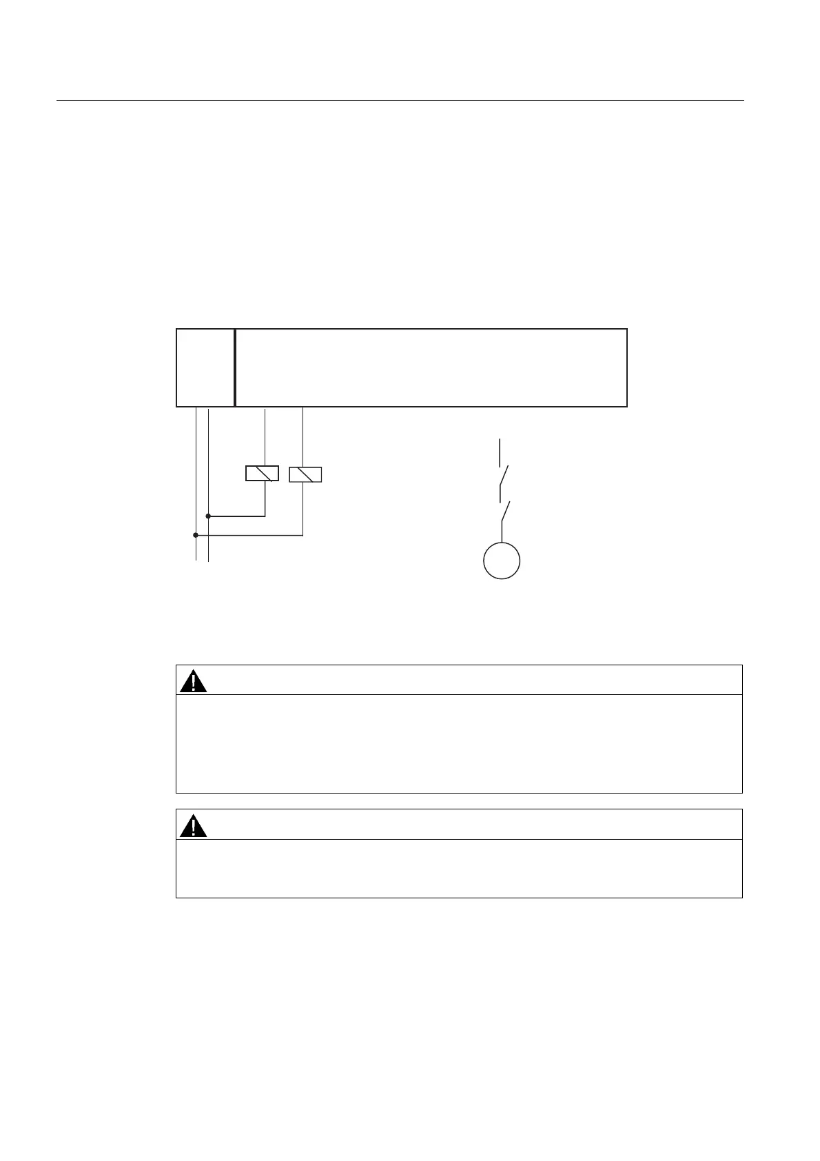
Use Case 2: Wiring Loads to L+ and M at Each Digital Output
You can switch two relays with one fail-safe digital output. The following conditions should be
kept in mind:
● L+ and M of the relays must be connected with L+ and M of the F-DO module (reference
potential must be equal).
● The normally open contacts of the two relays must be switched in series.
A connection to each of the four digital outputs is possible. The following figure shows an
example of the connection at DO 0. This circuit achieves SIL3/Category 4.
2L+ M
DO0
(M0)
DO0
(P0)
DO1
(M1)
DO1
(P1)
DO2
(M2)
DO2
(P2)
DO3
(M3)
DO3
(P3)
4/8 F-DI/4 F-DO
L+ M
K1
K1 K2
K2
M
2L+
Figure 8-19 Wiring Diagram for Each of Two Relays at One F-DO of the 4/8 F-DI/4 F-DO DC24V/2A
PROFIsafe Electronic Module
WARNING
When two relays are connected at one digital output (as shown in the figure above), "wire
break" and "overload" faults are detected only at the P-switch of the output (not at the M-
switch).
The controlled actuator can no longer be switched off in the event of a cross circuit between
the P- and M-switches of the output.
WARNING
To avoid cross circuits between P- and M-switches of a fail-safe digital output, you must
route the cables for the relay connection at the P- and M-switches to protect against cross
circuits (e.g., as separately sheathed cables or in separate cable ducts).