Fail-Safe Electronic Modules
8.1 8 /16 F-DI DC24V PROFIsafe Digital Electronic Module
ET 200pro Distributed I/O System - Fail-Safe Modules
Operating Instructions, 05/2007, A5E00394073-02
57
8.1.2 Terminal Assignment of 8/16 F-DI DC24V PROFIsafe Electronic Module
Terminal Assignment on CM IO 16×M12 Connection Module
The following table presents the terminal assignment of the 8/16 F-DI DC24V PROFIsafe
electronic module on the CM IO 16×M12 connection module.
Sockets X1 to X4 and X9 to X12 are assigned twice. This enables you to implement a 1oo2
evaluation with one connecting cable, e.g., channels 0 and 4 at connector X1.
The functional ground (FG) is located on the shield.
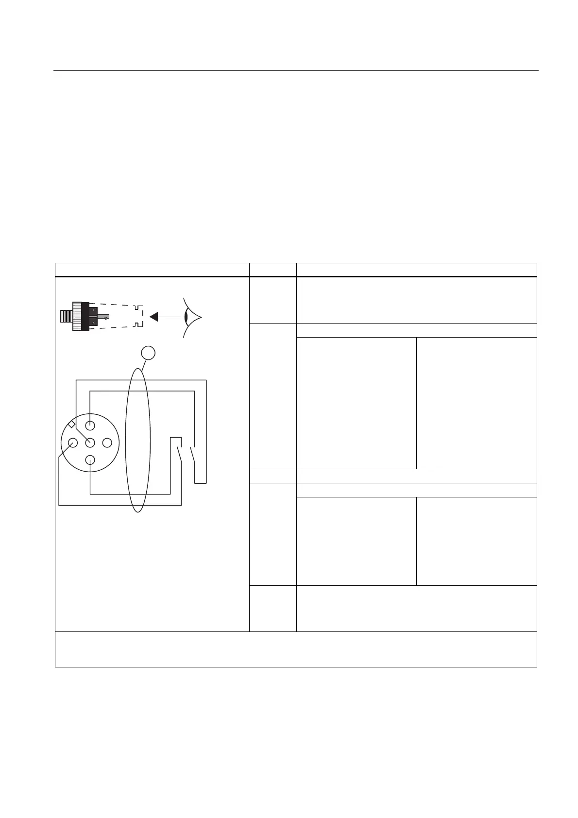
Table 8-1 Terminal Assignment on the CM IO 16xM12 Connection Module for 8/16 F-DI DC24V PROFIsafe
Circular connector view Terminal Assignment of X1 to X16
1 Connectors X1 to X4: 24 V sensor supply 1 (Vs1)
2
Connectors X5 to X8: 24 V sensor supply 2 (Vs2)
2
Connectors X9 to X12: 24 V sensor supply 3 (Vs3)
2
Connectors X13 to X16: 24 V sensor supply 4 (Vs4)
2
Input signal: 2
Connector X1: Channel 4
3
Connector X2: Channel 5
3
Connector X3: Channel 6
3
Connector X4: Channel 7
3
Connector X5: Not assigned
Connector X6: Not assigned
Connector X7: Not assigned
Connector X8: Not assigned
Connector X9: Channel 12
3
Connector X10: Channel 13
3
Connector X11: Channel 14
3
Connector X12: Channel 15
3
Connector X13: Not
assigned
Connector X14: Not
assigned
Connector X15: Not
assigned
Connector X16: Not
assigned
3 Sensor supply ground (1M)
Input signal: 4
Connector X1: Channel 0
Connector X2: Channel 1
Connector X3: Channel 2
Connector X4: Channel 3
Connector X5: Channel 4
Connector X6: Channel 5
Connector X7: Channel 6
Connector X8: Channel 7
Connector X9: Channel 8
Connector X10: Channel 9
Connector X11: Channel 10
Connector X12: Channel 11
Connector X13: Channel 12
Connector X14: Channel 13
Connector X15: Channel 14
Connector X16: Channel 15
5 Connectors X1 to X4: 24 V sensor supply 2 (Vs2)
3
Connectors X5 to X8: Not assigned
Connectors X9 to X12: 24 V sensor supply 4 (Vs4)
3
Connectors X13 to X16: Not assigned
1
3-, 4- or 5-core copper cable
2
Made available by the ET 200pro for the connected sensor
3
Relevant only in the case of 1oo2 evaluation via a connecting cable