Fail-Safe Electronic Modules
8.1 8 /16 F-DI DC24V PROFIsafe Digital Electronic Module
ET 200pro Distributed I/O System - Fail-Safe Modules
Operating Instructions, 05/2007, A5E00394073-02
77
Specific Characteristics for Fault Detection (Use Case 2.3)
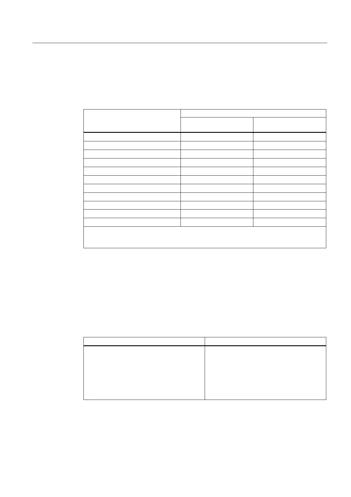
The following table summarizes fault detection according to the sensor supply and the
parameter assignment for the short-circuit test:
Table 8-10 F-DI Modules: Fault Detection (Use Case 2.3)
Fault detection in case of ... Example of fault
Internal sensor supply and
short-circuit test disabled
External sensor supply
Short circuit of DI 0 with DI 1 Yes* Yes*
Short circuit of DI 0 with DI 4 Yes Yes
Short circuit of DI 0 with DI 5 Yes* Yes*
P-short circuit of DI 0 Yes* Yes*
M-short circuit of DI 0 Yes* Yes*
Discrepancy error Yes Yes
P-short circuit of Vs1 No No
M-short circuit of Vs1, or Vs2 defective Yes Yes
Short circuit of Vs1 with Vs2 No No
Fault in read/test circuit Yes Yes
Supply voltage fault Yes Yes
*: Fault is detected only in case of signal corruption. That is, the signal read differs from the sensor
signal (discrepancy error). If there is no signal corruption relative to the sensor signal, fault detection
is not possible and is not required from a safety standpoint.
8.1.8 Use Case 3: Safety Mode SIL3/Category 4
Assigning Inputs to Each Other
The F-DI modules have 2, 8, or 16 fail-safe inputs (SIL2). A pair of these inputs can be used
as one input (SIL3). The following assignments apply in this case:
Table 8-11 Use Case 3: Assignment of Input Channels to Each Other
8/16 F-DI DC24V PROFIsafe 4/8 F-DI/4 F-DO DC24V/2A PROFIsafe
Input channel DI 0 and DI 4
Input channel DI 1 and DI 5
Input channel DI 2 and DI 6
Input channel DI 3 and DI 7
Input channel DI 8 and DI 12
Input channel DI 9 and DI 13
Input channel DI 10 and DI 14
Input channel DI 11 and DI 15
Input channel DI 0 and DI 4
Input channel DI 1 and DI 5
Input channel DI 2 and DI 6
Input channel DI 3 and DI 7