Fail-Safe Electronic Modules
8.1 8 /16 F-DI DC24V PROFIsafe Digital Electronic Module
ET 200pro Distributed I/O System - Fail-Safe Modules
78 Operating Instructions, 05/2007, A5E00394073-02
Sensor supply
The sensor must be supplied internally.
Table 8-12 Use Case 2: Assignment of Sensor Supply to Inputs
8/16 F-DI DC24V PROFIsafe 4/8 F-DI/4 F-DO DC24V/2A PROFIsafe
Input channels DI 0 to DI 3: Sensor supply Vs1
Input channels DI 4 to DI 7: Sensor supply Vs2
Input channels DI 8 to DI 11: Sensor supply Vs3
Input channels DI 12 to DI 15: Sensor
supply Vs4
Input channels DI 0 to DI 3: Sensor supply Vs1
Input channels DI 4 to DI 7: Sensor supply Vs2
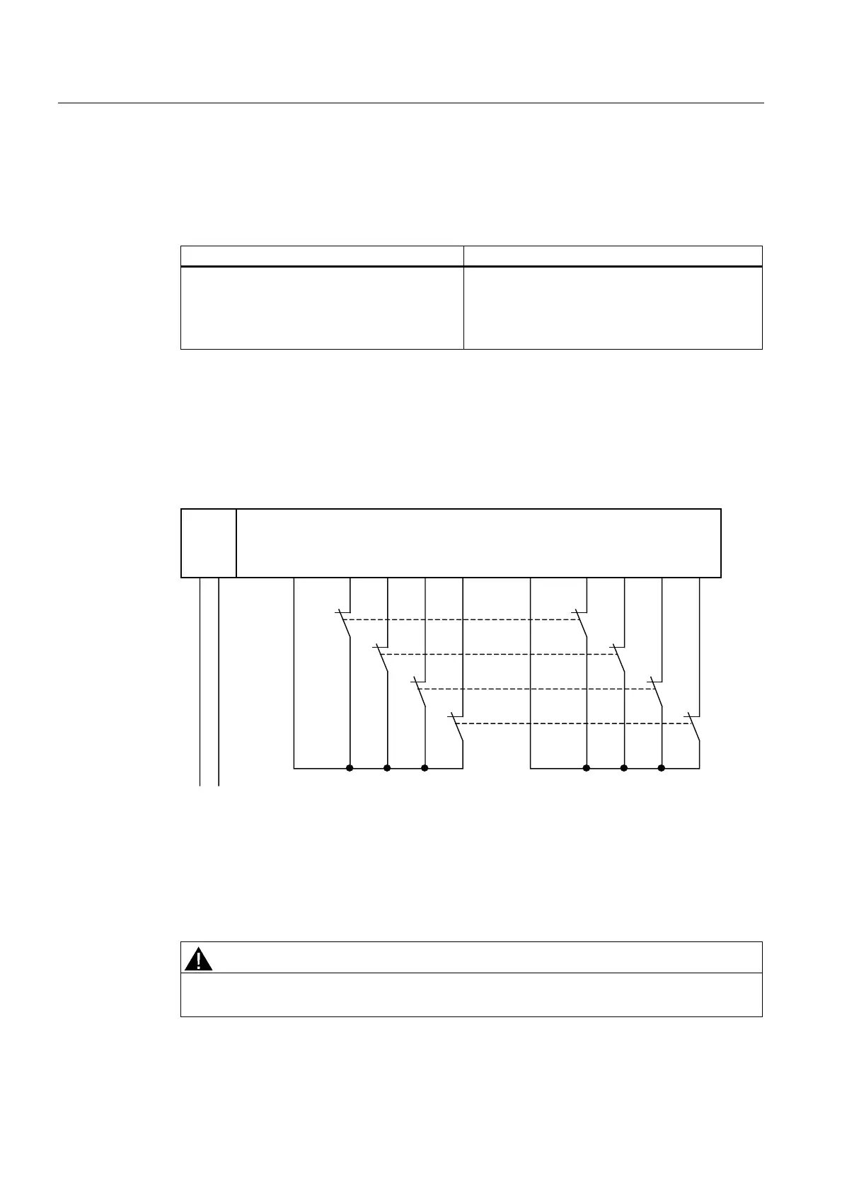
Wiring Diagram for Use Case 3.1 – Connecting One Two-Channel Sensor Via Two Channels
One two-channel sensor is connected via two channels to two inputs of the F-module for
each process signal (1oo2 evaluation).
The wiring is carried out at the appropriate connection module.
The figure below illustrates an example wiring diagram for channel groups 1 and 2.
8/16 F-DI
4/8 F-DI/4 F-DO
1L+ M DI0 DI1 DI2 DI3 DI4 DI5 DI6 DI7 Vs1 Vs2
L+ M
S0
S1
S2
S3
1L+
Sensor contacts are mechanically coupled.
Figure 8-13 Wiring Diagram for F-DI Modules - One Two-Channel Sensor Connected Via Two
Channels, Internal Sensor Supply
Alternatively, two one-channel sensors can be connected via two channels (see Figure
"Wiring Diagram for F-DI Modules - Two One-Channel Sensors Connected Via Two
Channels, Internal Sensor Supply"
). In this case, the same process variable is measured
with mechanically separated sensors.
WARNING
In order to achieve SIL3/Category 4 with this wiring, you must install a suitably qualified
sensor, for example, in accordance with IEC 60947.