Fail-Safe Electronic Modules
8.3 F -Switch PROFIsafe Digital Electronic Module
ET 200pro Distributed I/O System - Fail-Safe Modules
Operating Instructions, 05/2007, A5E00394073-02
129
8.3.9 Wiring of Outputs of the F-Switch PROFIsafe Electronic Module
Assignment of Channels
Channel Power bus
DO0 F0
DO1 F1
DO2 2L+
A list of the modules operated behind the F-Switch can be obtained on the Internet under ID
25371449.
Actuator Interconnection
The actuators are interconnected via the power bus.
The PP-switching outputs of the F-Switch PROFIsafe are fed to the actuators via the power
bus. The power bus is permanently wired within the system. As a result, only limited wiring
variations are possible. The power buses can be tapped and routed or conditioned only from
modules of the ET 200pro system.
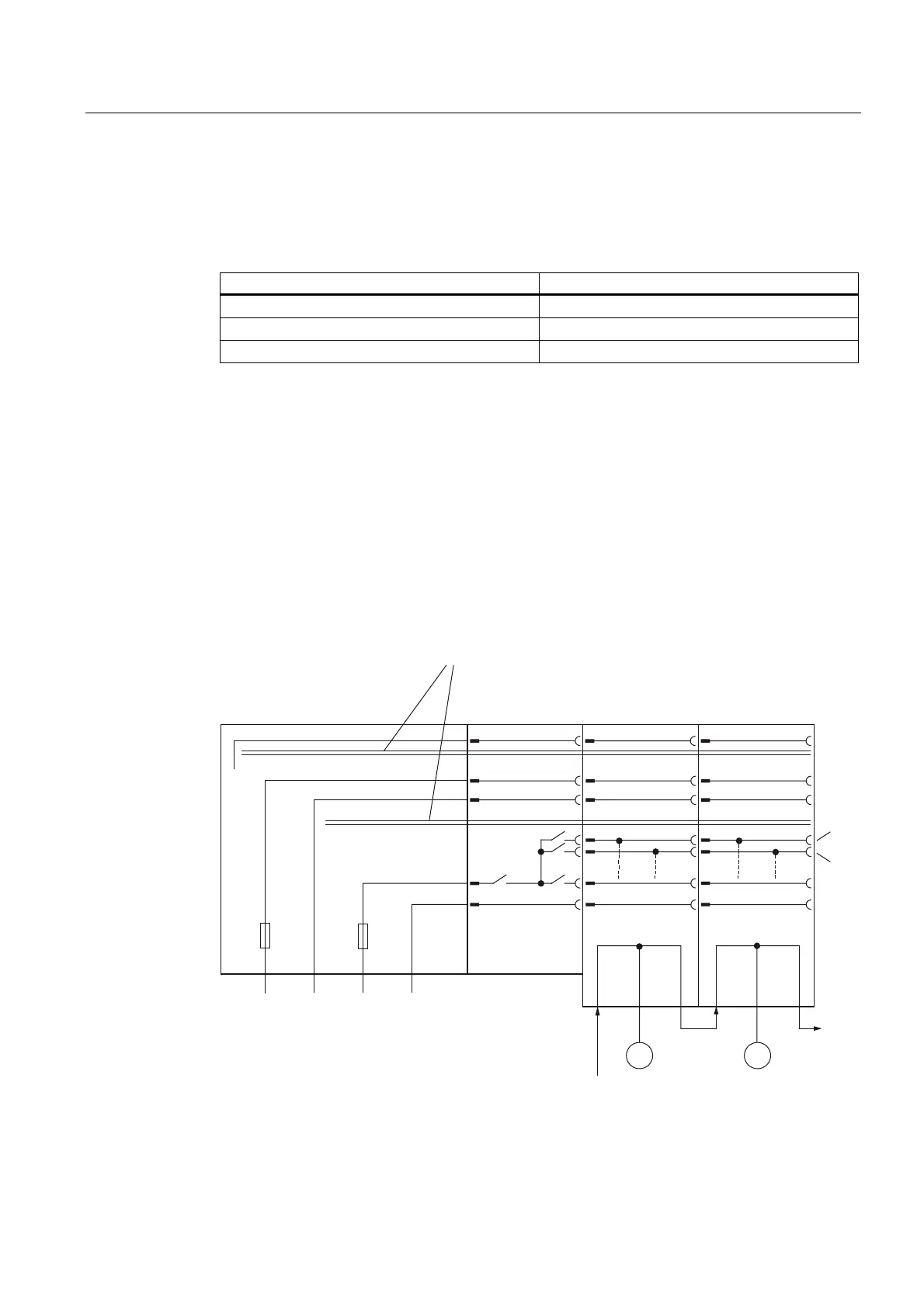
Wiring Diagram of Frequency Converter (SIL2/Category 3)
,0
/ 0 / 0
9
)
)
00
)6ZLWFK
)DLOVDIHIUHTXHQF\
FRQYHUWHU
(OHFWULFDOLVRODWLRQWKURXJKRSWRFRXSOHU
EDFNSODQHEXVSURFHVV
)DLOVDIH
IUHTXHQF\FRQYHUWHU
Figure 8-33 Wiring Diagram of F-Switch PROFIsafe - Connection of Frequency Converter