Fail-Safe Electronic Modules
8.3 F -Switch PROFIsafe Digital Electronic Module
ET 200pro Distributed I/O System - Fail-Safe Modules
Operating Instructions, 05/2007, A5E00394073-02
117
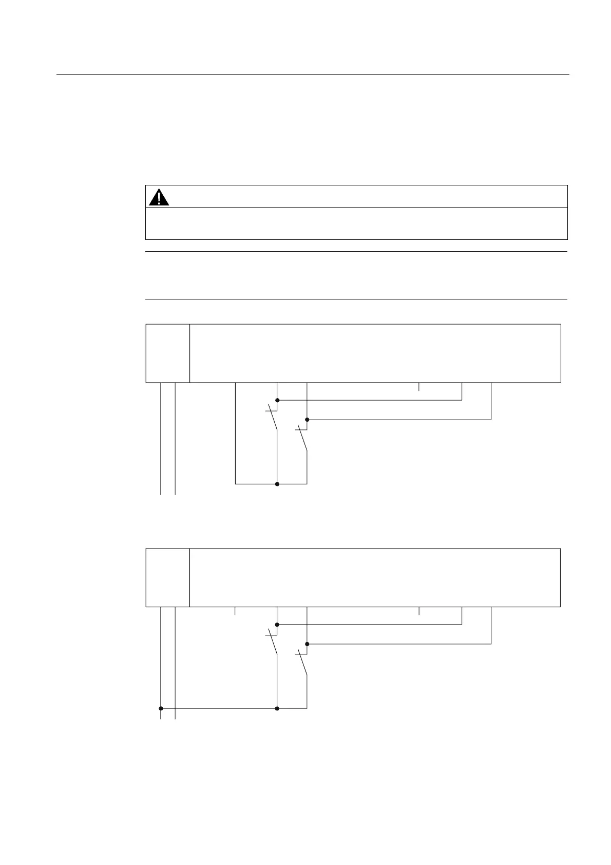
Wiring Diagram for Use Case 2.1 – Connecting One Sensor Via One Channel to Two Inputs
One sensor is connected via one channel to two inputs of the F-module for each process
signal (1oo2 evaluation).
The wiring is carried out at the appropriate connection module.
WARNING
In order to achieve SIL3/Category 3 with this wiring, you must install a suitably qualified
sensor, for example, in accordance with IEC 60947.
Note
If the voltage is supplied to the sensor from the F-Switch PROFIsafe electronic module, you
must use the internal sensor supply Vs1. Connection to Vs2 is not possible.
1L+
1L+ M
S0
S1
L+ M
Vs1 Vs2DI0 DI1 DI2 DI3
F-Switch
Figure 8-23 Wiring Diagram for F-Switch - One Sensor Connected Via One Channel to Two Inputs,
Internal Sensor Supply
1L+
1L+ M
S0
S1
L+ M
Vs1 Vs2DI0 DI1 DI2 DI3
F-Switch
Figure 8-24 Wiring Diagram for F-Switch - One Sensor Connected Via One Channel to Two Inputs,
External Sensor Supply