Fail-Safe Electronic Modules
8.3 F -Switch PROFIsafe Digital Electronic Module
ET 200pro Distributed I/O System - Fail-Safe Modules
126 Operating Instructions, 05/2007, A5E00394073-02
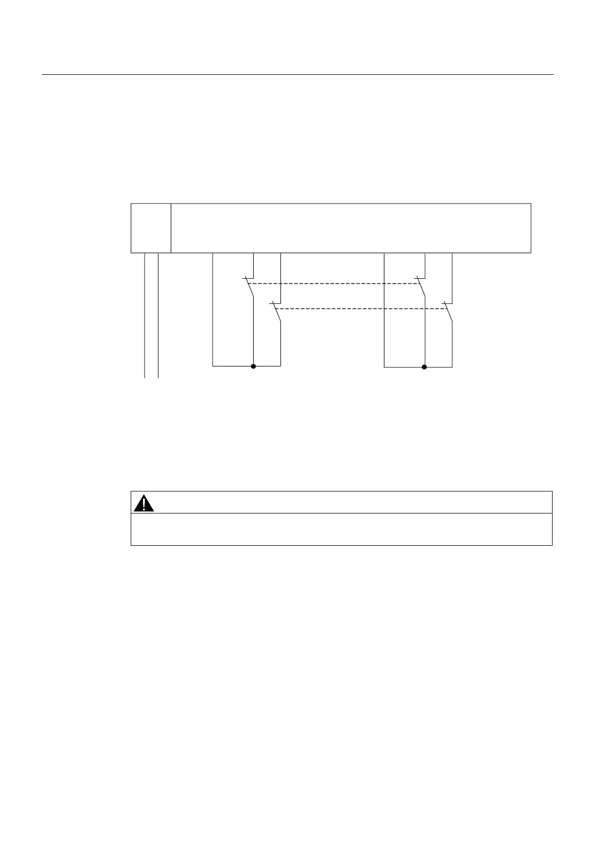
Wiring Diagram for Use Case 3.1 – Connecting One Two-Channel Sensor Via Two Channels
One two-channel sensor is connected via two channels to two inputs of the F-module for
each process signal (1oo2 evaluation).
The wiring is carried out at the appropriate connection module.
The figure below illustrates an example wiring diagram for channel groups 1 and 2.
F-Switch1L+
1L+ M
S0
S1
L+
M
Vs1 Vs2DI0 DI1 DI2 DI3
Sensor contacts are mechanically coupled.
Figure 8-31 Wiring Diagram for F-Switch - One Two-Channel Sensor Connected Via Two Channels,
Internal Sensor Supply
Alternatively, two one-channel sensors can be connected via two channels (see Figure
"Wiring Diagram for F-DI Modules - Two One-Channel Sensors Connected Via Two
Channels, Internal Sensor Supply"
). In this case, the same process variable is measured
with mechanically separated sensors.
WARNING
In order to achieve SIL3/Category 4 with this wiring, you must install a suitably qualified
sensor, for example, in accordance with IEC 60947.
Assignable Parameters for Use Case 3.1
Set the "Type of sensor interconnection" parameter to "2-channel equivalent" for the
corresponding input. Enable the "short-circuit test" parameter and set "internal" at the
"sensor supply" parameter.