Diagnostics
5.2 Error Diagnostics
ET 200pro Distributed I/O System - Fail-Safe Modules
36 Operating Instructions, 05/2007, A5E00394073-02
Diagnostics Using LED Display
Every fail-safe connection module indicates faults via its channel LED and SF LED (group
fault LED).
The channel LED and SF LED turn red as soon as a diagnostic function is triggered by the
F-module. The LEDs go out once all faults have been eliminated.
The SF LED flashes until you acknowledge passivation following a module fault.
Slave Diagnostics
The slave diagnostics comply with IEC 61784-1:2002 ED1 CP 3/1 or CP 3/3. The fail-safe
electronic modules support slave diagnostics in exactly the same way as the ET 200pro
standard modules.
For information about the universal structure of the slave diagnostics for ET 200pro and the
fail-safe modules, refer to the
ET
200pro Distributed I/O Device
manual. A supplementary
description of channel-specific diagnostics for fail-safe modules appears below.
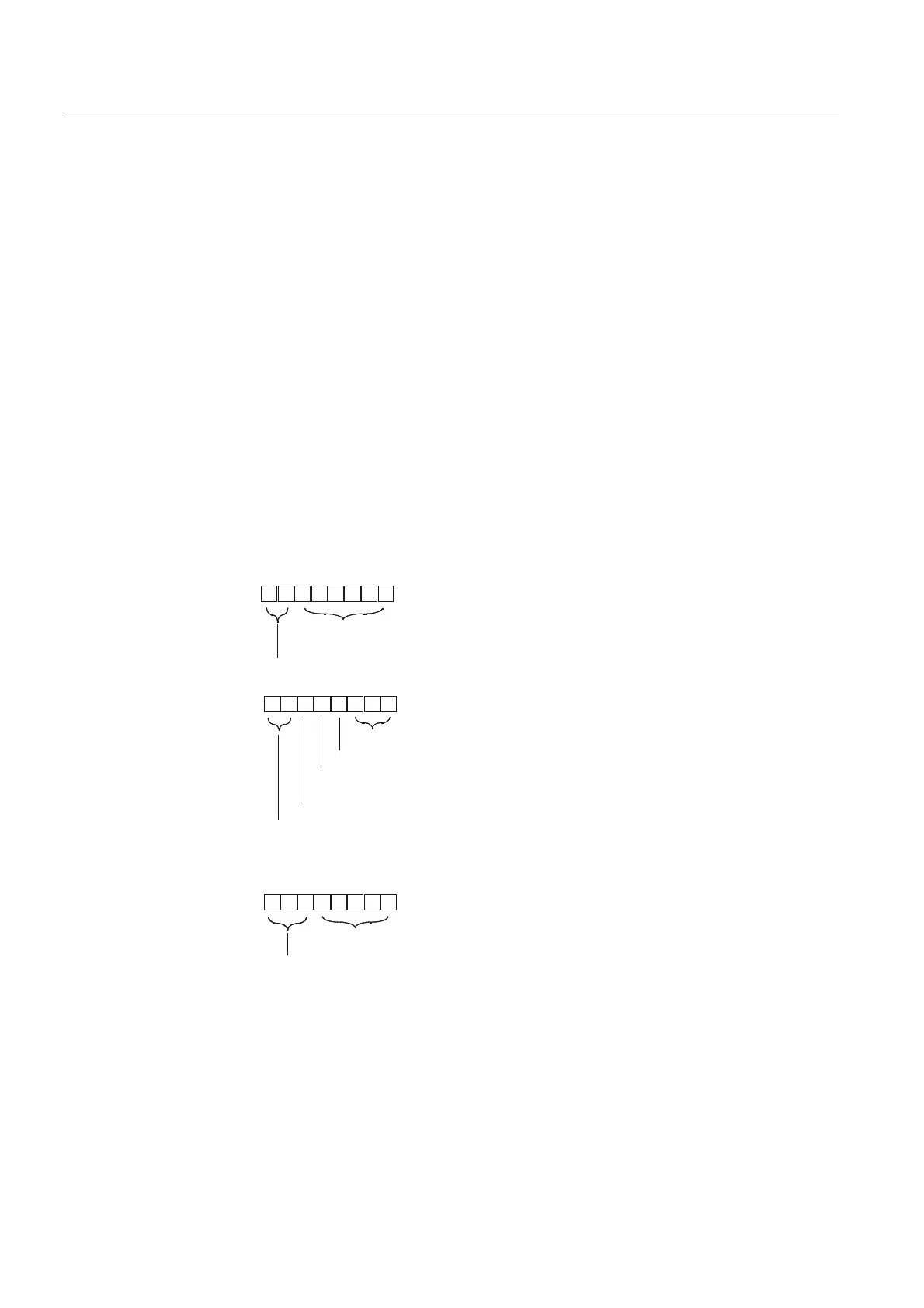
Channel-Specific Diagnostics
As with ET 200pro, there are three bytes available for each channel-specific diagnosis
starting at byte 19. A maximum of 10 channel-specific diagnostic messages are possible per
distributed I/O device. Channel-specific diagnostics for fail-safe modules are structured as
follows:
%LWQR
%LWQR
%LWQR
%
WR%
%
,GHQWLILFDWLRQQXPEHURIPRGXOH
VXSSO\LQJFKDQQHOVSHFLILFGLDJQRVWLFV
&RGHIRUFKDQQHOVSHFLILFGLDJQRVWLFV
%
WR
%
1XPEHURIFKDQQHOVXSSO\LQJGLDJQRVWLFV
%
,QSXWFKDQQHOGLJLWDOLQSXWVRIHOHFWURQLFPRGXOHV
%
2XWSXWFKDQQHOGLJLWDORXWSXWVRIHOHFWURQLFPRGXOHV
)DXOWW\SHVHHWDEOHEHORZ
&KDQQHOW\SH
%
ELW)',)',)'2)6ZLWFK
%
ELWV
%
ELWV
%
E\WH
%
ZRUG
%
ZRUGV
1H[WFKDQQHOVSHFLILFGLDJQRVWLFPHVVDJH
DVVLJQPHQWVDPHDVE\WHVWR
%\WHV
WR
0D[E\WH
,QWHUQDOIDXOW
2XWJRLQJGLDJQRVWLFPHVVDJH
,QFRPLQJGLDJQRVWLFPHVVDJH
$WOHDVWRQHIDXOWRQWKHPRGXOH
%\WH
%\WH
%\WH
Figure 5-1 Structure of Channel-Specific Diagnostics