Fail-Safe Electronic Modules
8.1 8 /16 F-DI DC24V PROFIsafe Digital Electronic Module
ET 200pro Distributed I/O System - Fail-Safe Modules
68 Operating Instructions, 05/2007, A5E00394073-02
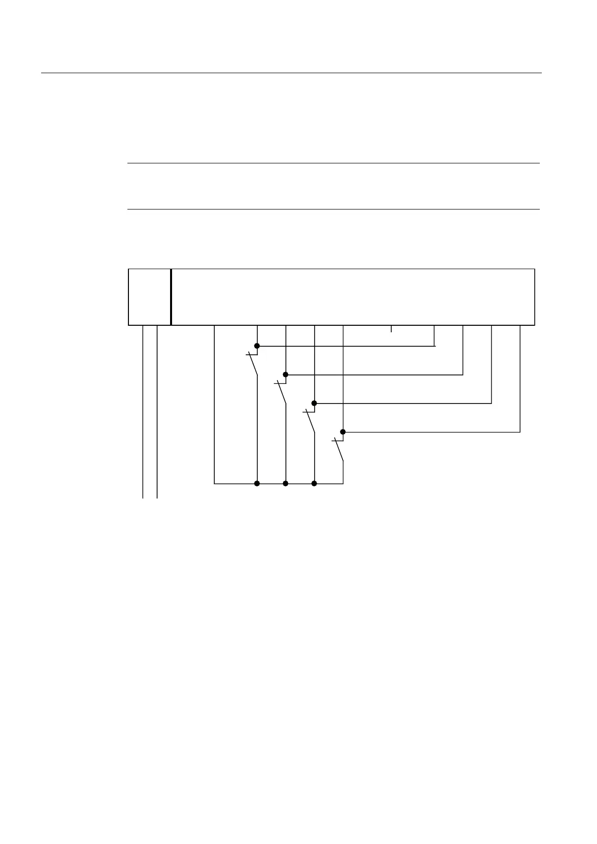
Wiring Diagram for Use Case 2.1 – Connecting One Sensor Via One Channel to Two Inputs
One sensor is connected via one channel to two inputs of the F-module for each process
signal (1oo2 evaluation).
Note
If the voltage is supplied to the sensor from the F-DI module, you must use the internal
sensor supply Vs1. Connection to Vs2 is not possible.
The wiring is carried out at the appropriate connection module.
The figures below illustrate an example wiring diagram for channel groups 1 and 2.
8/16 F-DI
4/8 F-DI/4 F-DO
1L+ M DI0 DI1 DI2 DI3 DI4 DI5 DI6 DI7 Vs1 Vs2
L+ M
S0
S1
S2
S3
1L+
Figure 8-5 Wiring Diagram for F-DI Modules - One Sensor Connected Via One Channel to Two
Inputs, Internal Sensor Supply