Fail-Safe Electronic Modules
8.1 8 /16 F-DI DC24V PROFIsafe Digital Electronic Module
ET 200pro Distributed I/O System - Fail-Safe Modules
74 Operating Instructions, 05/2007, A5E00394073-02
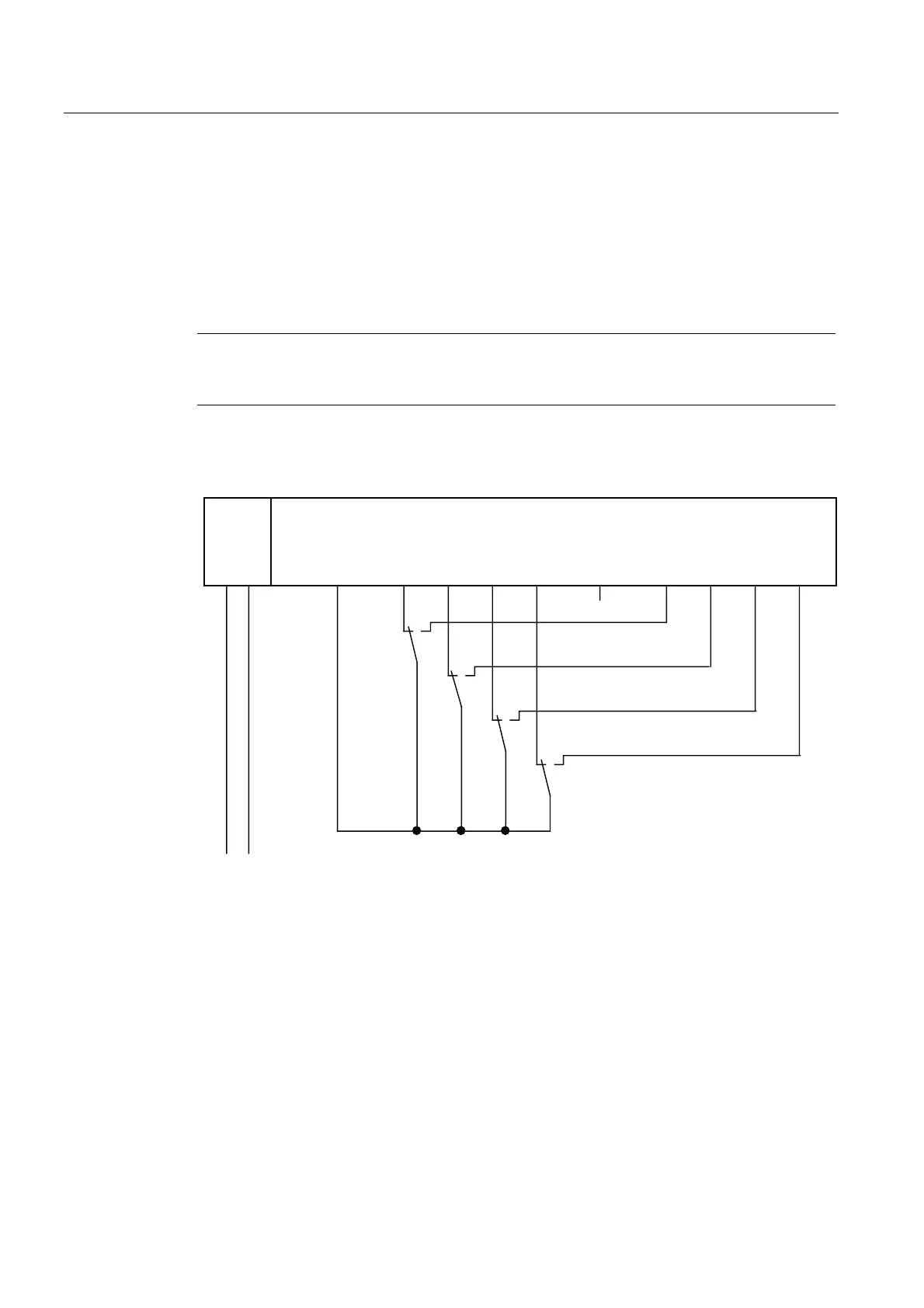
Wiring Diagram for Use Case 2.3 – Connecting One Nonequivalent Sensor Via Two Channels
Nonequivalently
One nonequivalent sensor is connected nonequivalently via two channels to two inputs of
the F-module for each process signal (1oo2 evaluation).
The left channels on the F-module (DI 0 to DI 2, DI 0 to DI 3, or DI 8 to DI 11) supply the
wanted signals. If no faults are detected, these signals will be available in the I/O area for
inputs in the F-CPU.
Note
If the voltage is supplied to the sensor from the F-DI module, you must use the internal
sensor supply Vs1 (or Vs3). Connection to Vs2 (or Vs4) is not possible.
The wiring is carried out at the appropriate connection module.
The figures below illustrate an example wiring diagram for channel groups 1 and 2.
)',
)',)'2
/ 0 ', ', ', ', ', ', ', ', 9V 9V
/ 0
6
6
6
6
/
7KHOHIWFKDQQHOVRQWKH)PRGXOHVXSSO\WKHZDQWHGVLJQDOV
Figure 8-10 Wiring Diagram for F-DI Modules - One Nonequivalent Sensor Connected
Nonequivalently Via Two Channels, Internal Sensor Supply