Technical Data and Characteristics
Cantilever force diagrams
1FT6 Synchronous Motors
3-128 Configuration Manual, (PFT6), 10.2005 Edition, 6SN1197-0AD02-0BP1
3.2 Cantilever force diagrams
Cantilever force stressing
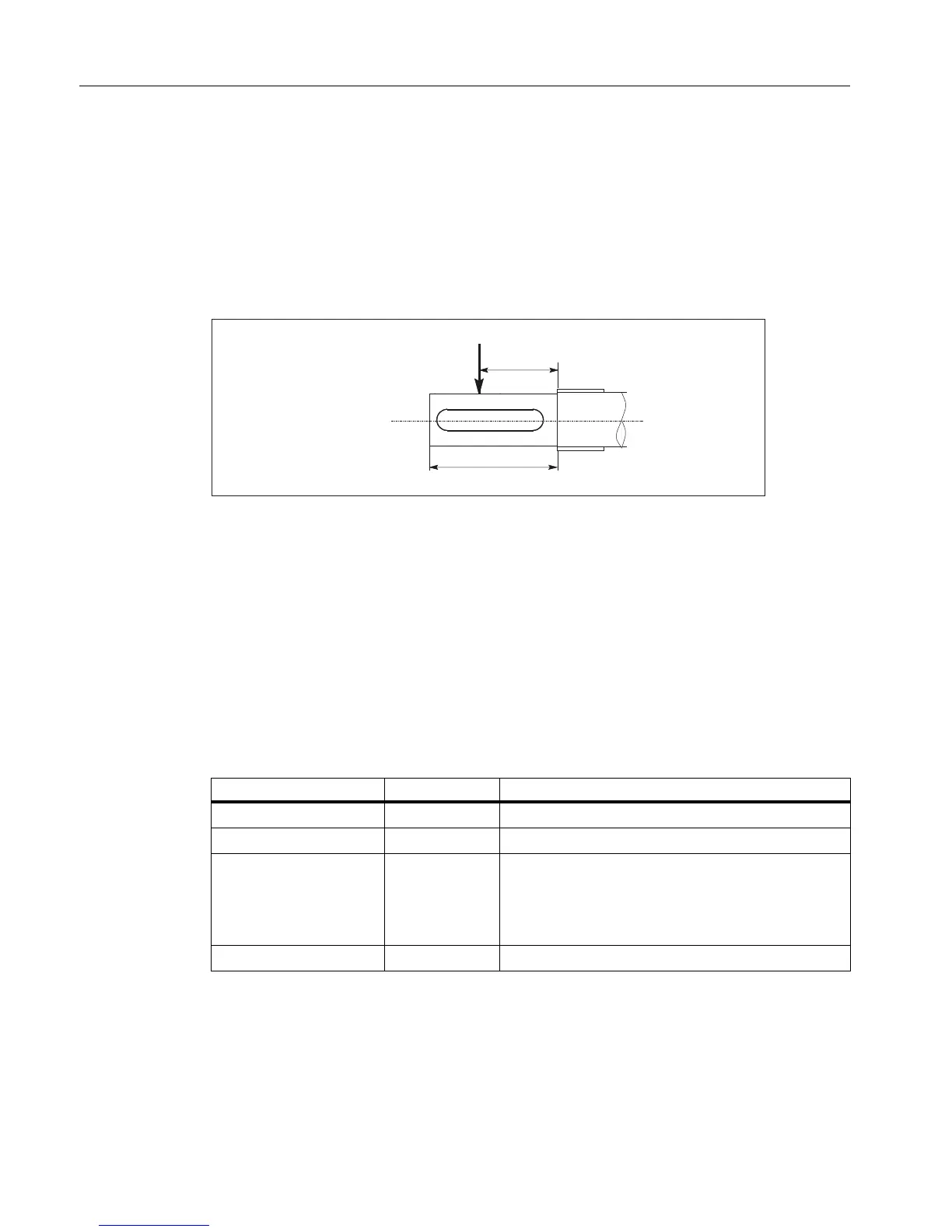
Point of application of cantilever forces F
Q
at the shaft end
• for average operating speeds
• for a nominal bearing lifetime of 20,000 h
Fig. 3-106 Force application point at the drive shaft end
Dimension x: Distance between the point of application of force F
Q
and the shaft shoulder in
mm.
Dimension l: Length of the shaft end in mm.
Calculating the belt pre-tension force F
R
When using other configurations, the actual forces generated from the torque being trans-
ferred must be taken into account.
)
4
[
O
F
R
[N] = 2 • M
0
• c / d
R
F
R
= F
Qper
Table 3-67 Explanation of the formula abbreviations
Formula abbreviations Units Description
F
R
N Belt pre-tension
M
0
Nm Motor stall torque
c ––– Pre-tensioning factor; the pre-tensioning factor is an
empirical value from the belt manufacturer.
It can be assumed as follows:
for toothed belts: c = 1.5 to 2.2
for flat belts c = 2.2 to 3.0
d
R
m Effective diameter of the belt pulley

 Loading...


