VS
07.94
1-106
Siemens AG 1997 All Rights reserved
SIMODRIVE 611A Installation and Start–Up Guide/IAA/–04.97 Edition
e) Speed setpoint adaptation
If the adjustment range of the tachometer potentiometer is not sufficient (for lo-
wer speed range), then the speed setpoint can be adapted via a setpoint vol-
tage divider circuit. The following circuit diagram is valid:
virt. M
R
x
Speed controller
20 k
20 k
N
set
The following relationship is obtained for R545 (R546):
n
required
R
x
=10k
n
rated
– n
required
f) Limiting, speed controller I component (refer to2.7)
The maximum speed controller I component can be limited by mounting R547
(R550).
g) Electronic weight equalization
The value to be set for the electronic weight equalization is obtained from the
current setpoint I
setGwa
which can be measured at the test socket T for the axis
to be enabled, at standstill (N
set
=0).
R=
I
SetGwa
10k
10V
Caution: I
SetGwa
5V R20 k!
After mounting, the value at test socket T must be able to be measured with the
same polarity, with the axis inhibited.
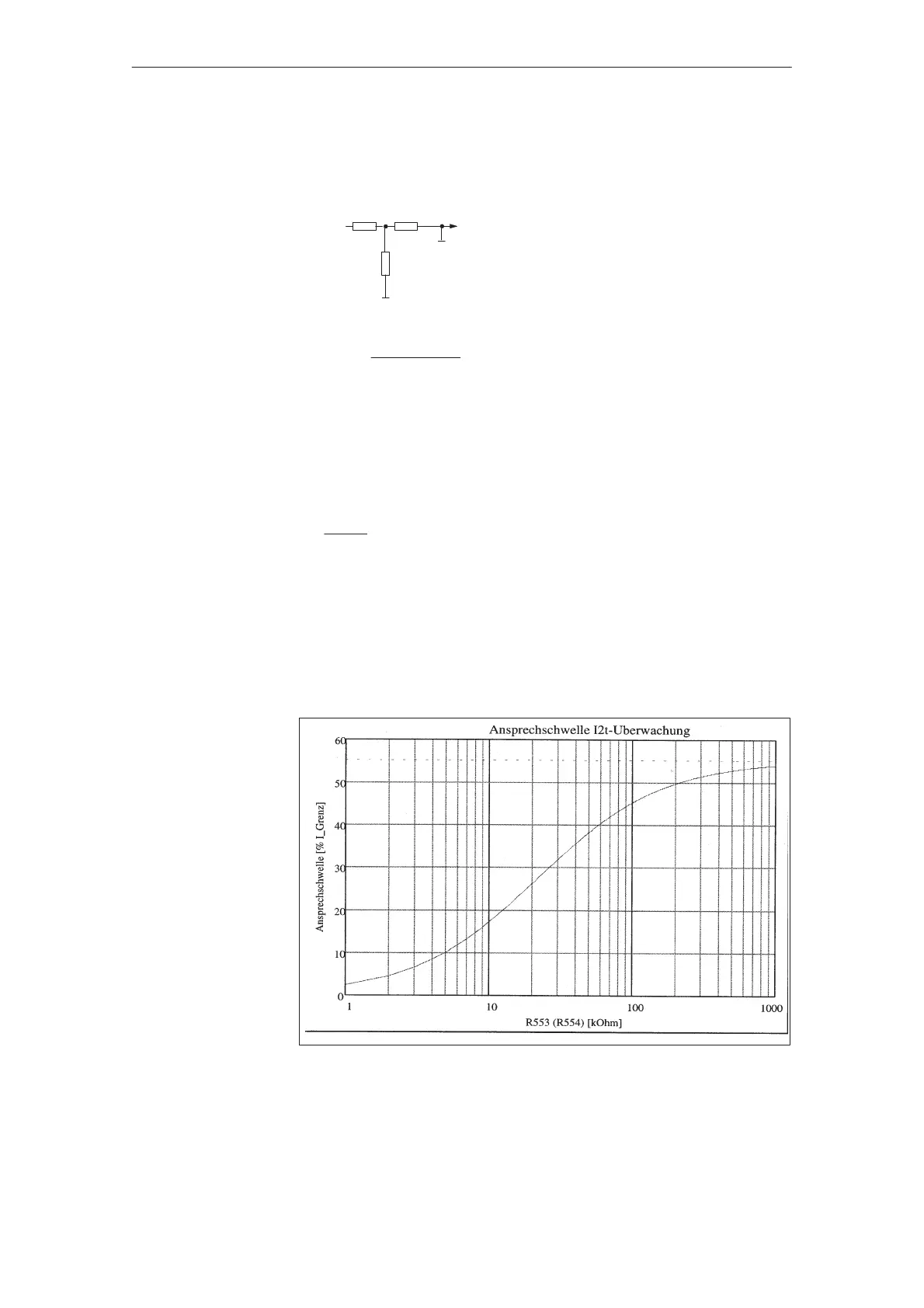
h) Response threshold I
2
t-monitoring
The I
2
t monitoring limits the current setpoint to a thermally permissible value.
The response threshold is 55% of the power module peak current, and, when
required, can be reduced corresponding to the following characteristic, by
mounting R553 (R554):
Fig. 3-2
Feed modules (VS)
04.973.1.1 Dimensioning the setting elements (standard interface) 04.97