VS
07.94
1-105
Siemens AG 1997 All Rights reserved
SIMODRIVE 611A Installation and Start–Up Guide/IAA/–04.97 Edition
c) Tachometer adaptation
The following equivalent circuit diagram is valid for the individual tachometer
voltages:
4 k
R
x
V
tach.X
8 k
20 k
The tachometer voltage V
tach
is normally 40 V at
rated speed, which results in a voltage
tachoX
of 10
V. For a rated speed which significantly deviates
from the rated motor speed, it is possible to re–di-
mension corresponding to this criterium.
The following formula is valid:
(
5k
–1
V
tach.
V
tach.X
)
–7.5k
1
4
(
V
tach.
V
tach.X
)
][
R
x
=
V
tach.
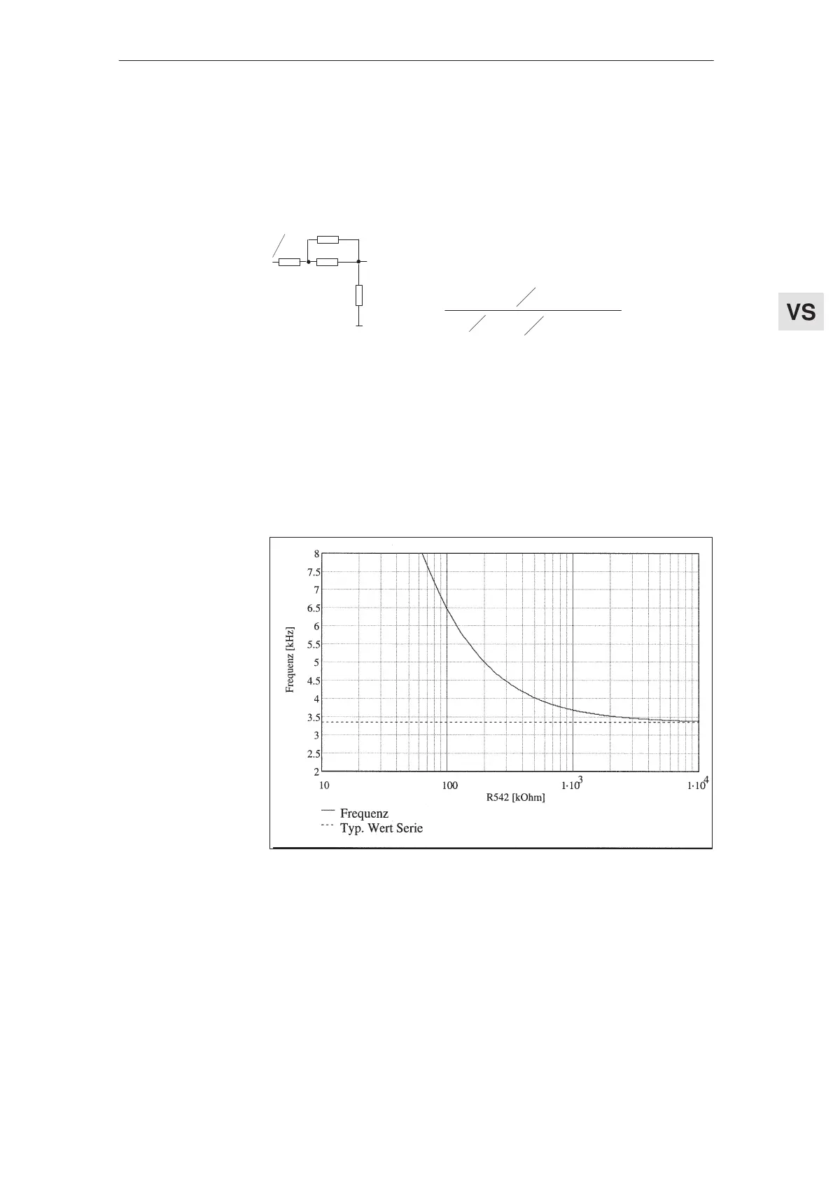
d) clock frequency PBM
If noise problems occur (the motor makes a whistling sound), then the PWM
inverter clock frequency can be changed for both axes together.(Fig. 3–1)
In this case, it must be observed that the available current ( I
n
, I
max
) is re-
duced when the clock frequency is increased (refer to Pj, Section 4.1).
The I
2
t limiting is set in the factory to a pulse frequency of 3.3 kHz and a maxi-
mum ambient temperature of 40
C. If these values are exceeded (pulse fre-
quency and/or ambient temperature), the response threshold must be adapted
(refer to Fig. 3-2).
Fig. 3-1
Feed modules (VS)
04.97 3.1.1 Dimensioning the setting elements (standard interface)