VS
07.94
1-113
Siemens AG 1997 All Rights reserved
SIMODRIVE 611A Installation and Start–Up Guide/IAA/–04.97 Edition
Start–up with main spindle drive option
The settings for the control parameters for C–axis operation on the parameter
board, control parameters for main spindle drive operation, on the option board.
The main spindle drive option components which have to be modified, are
mounted on solder pins (layout, refer to Section 9).
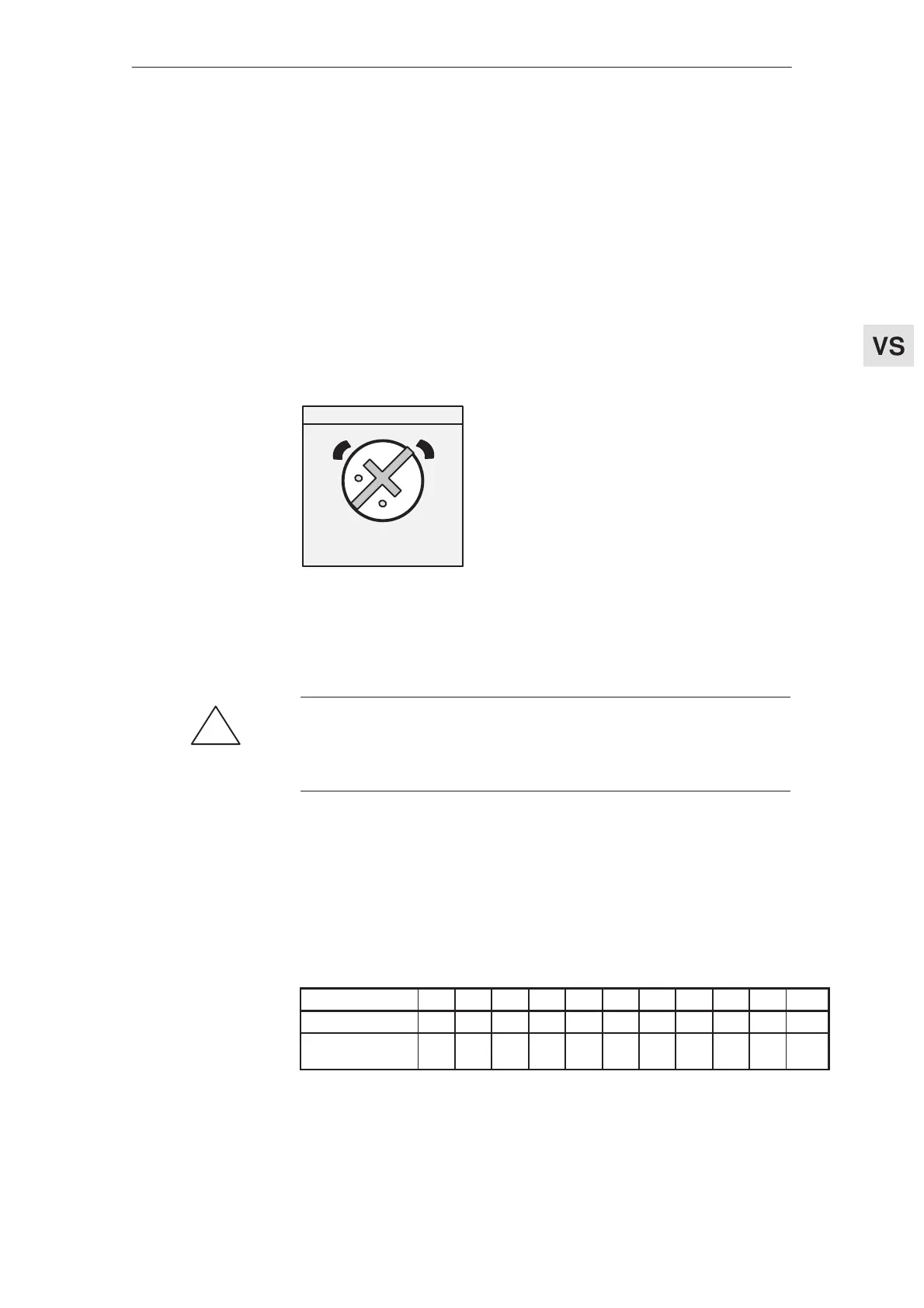
The potentiometer scale divisions (in the setting tables) are defined as follows:
8
9/
10
7
6
5
4
3
2
0/1
5
1
2
3
4
9
8
7
6
The setting shown in the diagram
corresponds to 7 scale divisions.
10
0
Pre–settings
!
Warning
Parameter board changes: Remove R4, R5 and R54 and, if necessary, C4
(when supplied this is not mounted).
If this is not observed, it could result in undesirable axis motion!
Settings with the control board removed
Table 5-1 Ramp–up time from 0 V to 10 V in s via terminal 56/14, set using potentiometer
R20 and terminal 102
0 1 2 3 4 5 6 7 8 9 10
Term.102 open 0.01 0.11 0.21 0.31 0.4 0.5 0.6 0.7 0.8 0.9 1.11
Term.102 to
term. 9
0.1 1.08 2.07 3.06 4.04 5.03 6.02 7.01 8.01 9.04 11.05
The ramp–up time range via R20 can be changed by modifying R27/R60.
Ramp–up time
Feed modules (VS)
04.97 5.1 Pre–settings