VS
07.94
1-114
Siemens AG 1997 All Rights reserved
SIMODRIVE 611A Installation and Start–Up Guide/IAA/–04.97 Edition
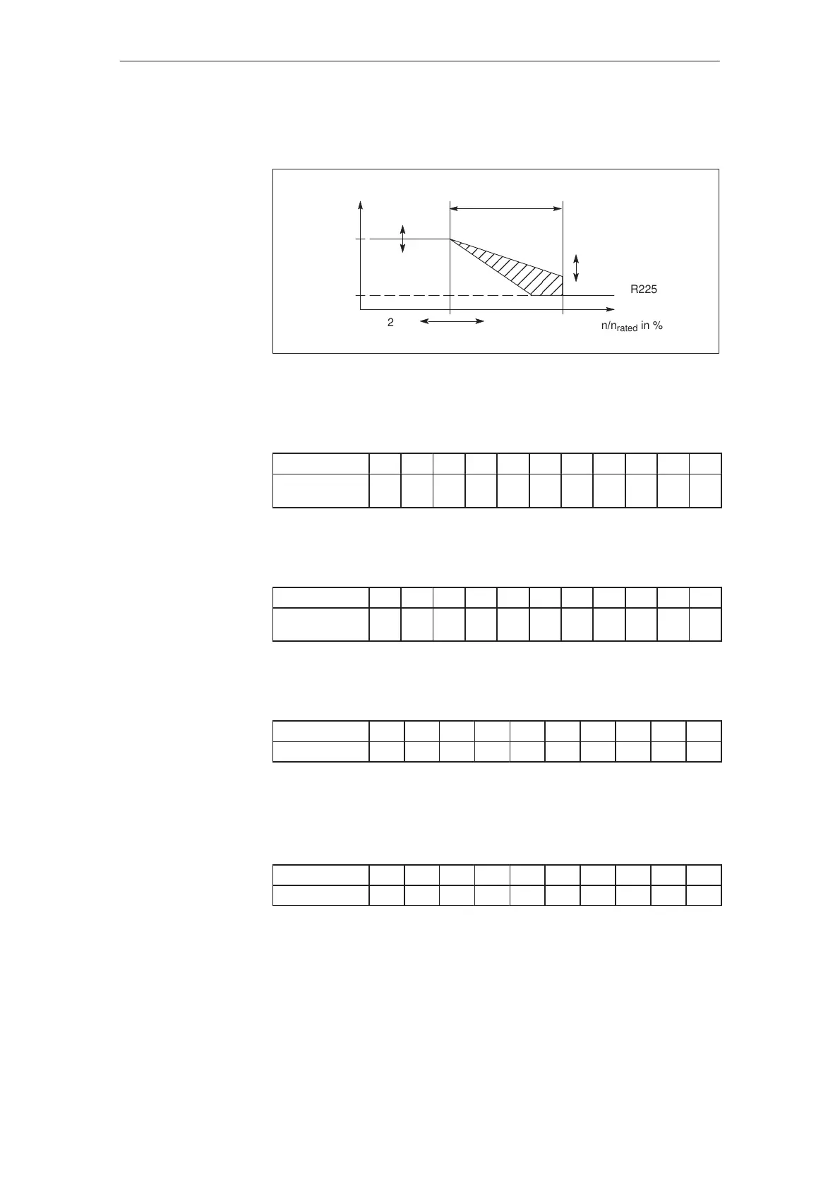
100
13
R214
R213
”Constant power”
range
R76
I/I
max
n/n
rated
in %
R225
23 70 100
Fig. 5-1 Torque limiting
Table 5-2 Adjustable start of the ”constant power” range referred to n
max
= 10 V in
% via R214
Pot. R214
0 1 2 3 4 5 6 7 8 9 10
Start of the
range in %
70 65 60 55 50 45 40 35 30 26 22
Table 5-3 Deviations of the selected power to constant power at the point n
max
in %
via R213
Pot. R213
0 1 2 3 4 5 6 7 8 9 10
Deviation
in %
+20 0 –20
Table 5-4 Constant torque limiting I
set
/I
max
in % via R76 (solder pins), R76 is open
when supplied
R76 in kΩ 3 4.3 6.2 8.2 11 15 18 22 27 36
I
set
/I
max
in % 10 20 30 40 50 60 70 80 90 100
Intermediate values can be determined by interpolating
Table 5-5 Speed–dependent torque limiting I
set
/I
max
in % via R225 (solder pins) for
R226 = 20 kΩ
R225 in kΩ
2.4 4.7 7.5 11 16 22 30 47 70 100
I
set
/I
max
in % 1 10 20 30 40 50 60 70 80 85
12 % I
set
/I
max
are set as standard. Intermediate values are obtained by interpo-
lating.
Torque
limiting
Feed modules (VS)
04.975.1.1 Settings with the control board removed